


OM--04760 SELF-PRIMING CENTRIFUGAL PUMPS
PAGE B -- 6 INSTALLATION
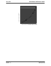
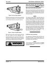
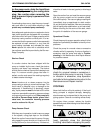
Figure2.ValveinOpenPosition
During the priming cycle, air from the pump casing
flowsthroughthebypassline,andpassesthrough
theAirReleaseValvetothewetwell(Figure2).
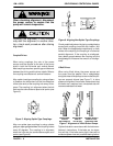
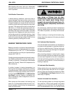
Figure 3. Valve in Closed Position
When the pump is fully primed, pressure resulting
from flow against the valve diaphragm com-
presses the spring and closes the valve (Figure 3).
The valve will remain closed, reducing the bypass
of liquid to 1 to 5 gallons (3.8 to 19 liters) per min-
ute, until the pump loses its prime or stops.
Some le akage (1 to 5 gallons or 3.8 to 19
liters per minute ) will occur when the
valve is fully closed. Be sure
the bypass
line is directed back to the wet well or
tank to prevent hazardous spills.
When the pump shuts down, the spring returns the
diaphragm t o its original position. Any solids that
may have accumulated in the diaphragm chamber
settle to the bottom and are flushed out during the
next priming cycle.
NOTE
The valve will remain open if the pump does not
reach its designed capacity or head. Valve closing
pressure is dependent upon the discharge head of
the pump a t full capacity. The range of the valve
closing pressure is established by the tension rate
of th espring as ordered from thefactory. Valveclos-
ing pressure can be further adjusted to the exact
system requirements by moving the spring retain-
ing pin up or down the plunger rod to increase or
decrease tension on the spring. Contact your Gor-
man -Rupp distributor or the Gorman-Rupp Com-
pany for information about an Automatic Air Re-
lease Valve for your specific application.
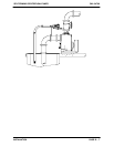
Air Release Valve Installation
The Automatic Air Release Valve must be inde-
pendently mounted in a horizontal position and
connected to the discharge line of the self-priming
centrifugal pump (see Figure 4).
NOTE
If the Air Release Valveis to beinstalled on astaged
pump application, contact the factory for specific
installation instructions.