


7
78-8126-0432-6-A
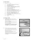
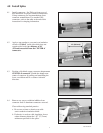
4.5 Apply red compund on cable insulation, making
certain to fill in edges of cable semi-cons.
Note: DO NOT use silicone grease.
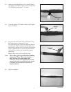
4.6 Position each splice body over the connector and
align the leading end of the rubber part with the
center of the marker tape.
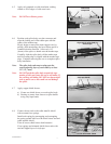
Slowly begin to remove the inner support core by
pulling, while unwinding, the loose ribbon end in a
counterclockwise direction. Allow only 1/4"
(6 mm) of the splice to shrink onto the marker tape.
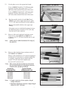
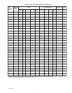
Carefully slide the splice body off the marker tape
until its leading edge is aligned with the marker tape
edge. Continue removing the core to complete splice
body installation.
Note: The splice body ends must overlap onto the
semi-conducting layer of each cable by at least
1/2" (12,7 mm).
Note: DO NOT push the splice body towards the tape
marker, as this may cause the end to roll under. If
the end does roll under, DO NOT use sharp edged
tools to pull it out as this could cut and damage
the splice.
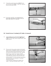
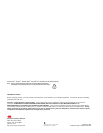
4.7 Apply copper shield sleeves:
a) Center one shield sleeve over each splice body.
b) Starting at center, form sleeves to splice bodies
using vinyl tape bands.
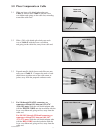
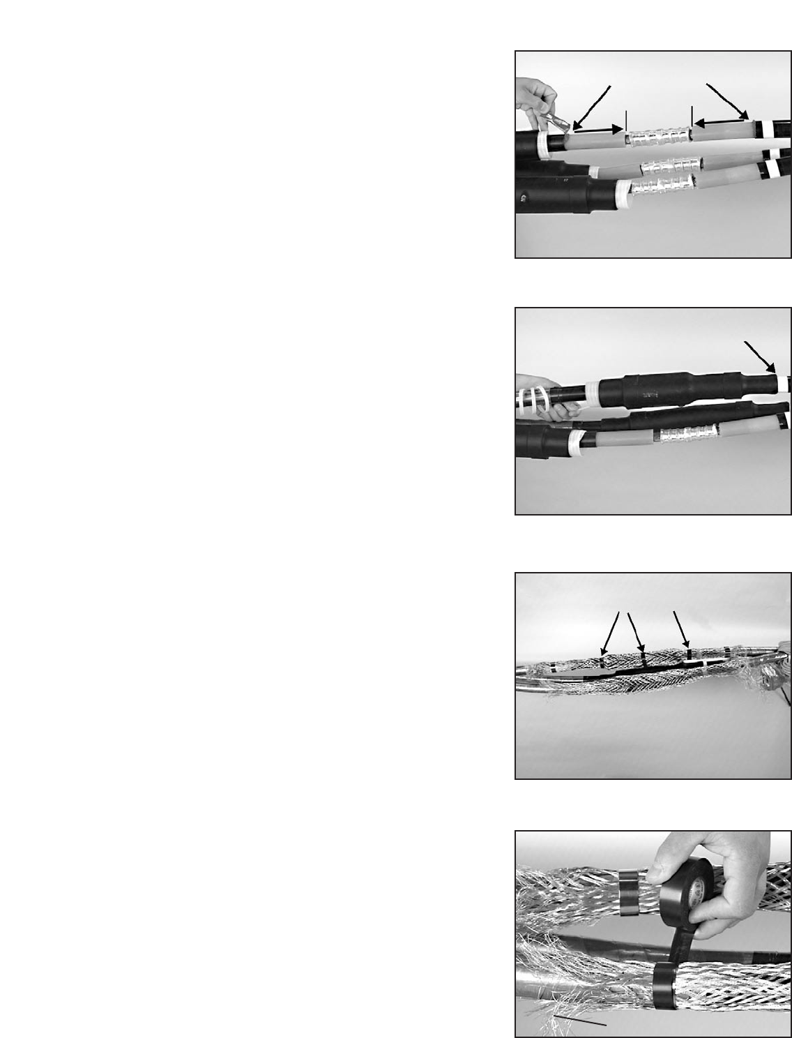
4.8 Connect sleeve ends to the cable metallic shield
with constant force springs.
Install each spring by unwrapping and rewrapping
the spring around itself over the shield sleeve end and
cable metallic shield.
Trim off excess shield sleeve braid material.
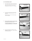
Cover springs and trimmed shield sleeve ends with
one half-lapped layer of vinyl tape.
Red P55/R
compound
vinyl tape bands
align end of splice body to
marker tape
trim off excess sleeve