


4
78-8126-0432-6-A
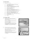
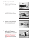
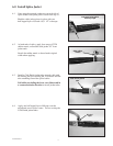
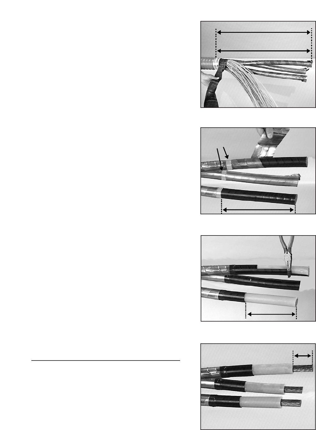
2.3 Cut the phase cores to the appropriate length.
Cores of Cable X should be 33" (838 mm) when
measured from the cable jacket end or 31 1/2"
(800 mm) when measured from end of the armor.
Cores of Cable Y should be 25" (635 mm) when
measured from the cable jacket end or 23 1/2"
(597 mm) when measured from end of the armor.
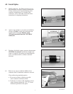
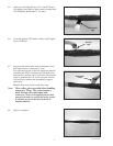
2.4 Bind the metallic shields of both Cable X and
Cable Y cores with a copper tape strip at a point
11 1/2" (292 mm) from the end of each conductor.
Remove the metallic shields to the copper tape
binding.
If the phase cores are individually jacketed, remove
the individual jackets a distance of 15" (381 mm)
from the end of each conductor.
Cable X 33" (838 mm)
Cable Y 25" (635 mm)
copper
tape strips
8 1/2" (216 mm)
11 1/2" (292 mm)
field determine
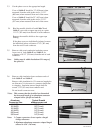
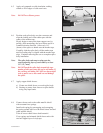
2.5 Remove cable semi-conductive insulation screen
from cores of both Cable X and Cable Y for
a distance of 8 1/2" (216 mm) from the end of each
conductor.
Note: Cables must be within Insulation O.D. range of
the splice kit.
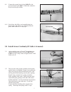
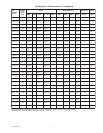
2.6 Remove cable insulation from conductors ends of
both Cable X and Cable Y.
Remove cable insulation for 1/2 connector length plus
an allowance * for increases in connector length due
to crimping. Insulation removal length shall not
exceed 3 1/4" (83 mm) from conductor end.
Do not install connectors now.
*Note: This assumes that the installer has determined
the increased length of an aluminum connector
crimped with a specific tool and die.
Aluminum Typical Growth
Connector Size allowance per end
1/0 AWG 1/8" (3 mm)
2/0 AWG 1/8" (3 mm)
3/0 AWG 1/8" (3 mm)
4/0 AWG 1/4" (6 mm)
250 kcmil 1/4" (6 mm)
350 kcmil 1/4" (6 mm)
Notes: 1. Copper connectors do not require a length
change allowance.
2. Maximum aluminum connector crimped length
allowed is 6.50" (165 mm).