840569-YTG-A-0612
2 Johnson Controls Unitary Products
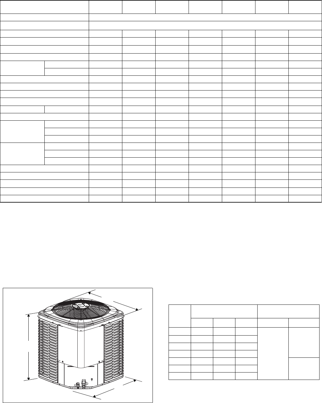
All dimensions are in inches. They are subject to change with-
out notice. Certified dimensions will be provided upon request.
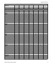
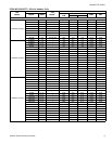
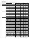
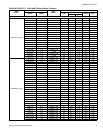
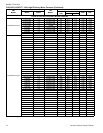
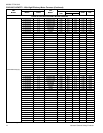
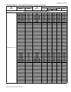
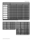
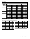
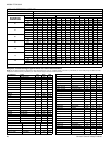
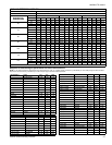
Physical and Electrical Data
MODEL
YCJD18
S41S1(H)(E)
YCJD24
S41S1(H)(E)
YCJD30
S41S1(H)(E)
YCJD36
S41S1(H)(E)
YCJD42
S41S2(H)(E)
YCJD48
S41S1(H)(E)
YCJD60
S41S1(E)
Unit Supply Voltage 208-230V, 1 60Hz
Normal Voltage Range
1
187 to 252
Minimum Circuit Ampacity
10.0 12.4 14.7 17.9 21.5 21.1 34.3
Max. Overcurrent Device Amps
2
15 20 25 30 35 35 60
Min. Overcurrent Device Amps
3
15 15 15 20 25 25 35
Compressor Type
Rotary Recip Recip Recip Recip Recip Scroll
Compressor Amps
Rated Load
7.6 9.3 10.6 13.1 16 15.7 26.2
Locked Rotor
40 43 54 74 88 84 150
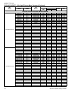
Crankcase Heater
No No No No No No No
Factory External Discharge Muffler
No No No No No Yes No
Factory External Check Valve
No No No No No No No
HS Kit Required with TXV
4
Yes Yes Yes Yes Yes Yes No
Fan Motor Amps Rated Load
0.5 0.8 1.4 1.5 1.5 1.5 1.5
Fan Diameter Inches
17.5 17.5 17.5 22.0 22.0 22.0 24.0
Fan Motor
Rated HP
1/12 1/8 1/4 1/4 1/4 1/4 1/4
Nominal RPM
1100 1075 1100 850 850 850 850
Nominal CFM
1400 1950 2050 3200 3050 2950 3600
Coil
Face Area Sq. Ft.
9.60 9.60 9.60 13.07 14.16 14.16 18.68
Rows Deep
1 1 1 1 1 1 1
Fin / Inches
23 23 23 23 23 23 23
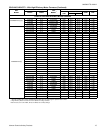
Liquid Line Set OD (Field Installed)
3/8 3/8 3/8 3/8 3/8 3/8 3/8
Vapor Line Set OD (Field Installed)
5/8 3/4 3/4 3/4 7/8 7/8 7/8
Unit Charge (Lbs. - Oz.)
5
3 - 3 3 - 13 3 - 14 4 - 9 4 - 10 4 - 9 5 - 6
Charge Per Foot, Oz.
0.58 0.62 0.62 0.62 0.67 0.67 0.67
Operating Weight Lbs.
97 129 131 145 164 173 195
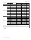
Models with "H" on the end of the model number are shipped with a Hard Start Kit installed at the factory.
Models with “E” on the end of the model number have an ElectroFin® coating on the outdoor coil.
1. Rated in accordance with AHRI Standard 110-2012, utilization range “A”.
2. Dual element fuses or HACR circuit breaker. Maximum allowable overcurrent protection.
3. Dual element fuses or HACR circuit breaker. Minimum recommended overcurrent protection.
4. See Hard Start Kit Accessory Installation Manual for Hard Start Kit part number for each model.
5. The Unit Charge is correct for the outdoor unit, smallest matched indoor unit, and 15 feet of refrigerant tubing. For tubing lengths other than 15 feet, add or
subtract the amount of refrigerant, using the difference in length multiplied by the per foot value.
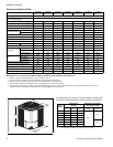
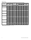
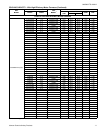
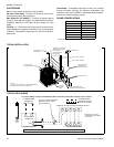
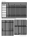
Unit
Model
Dimensions
(Inches)
Refrigerant Connection
Service Valve Size
A
1
1. Overall height from bottom of base pan to top of fan guard.
B C Liquid Vapor
18 28
23-1/2 23-1/2
3/8”
3/4”
24 28 23-1/2 23-1/2
30 28 23-1/2 23-1/2
36 28 29 29
42 30 29 29
7/8”48 30 29 29
60 32 33-5/8 33-5/8