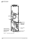
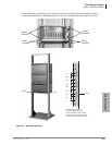
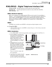
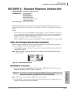
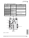
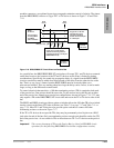
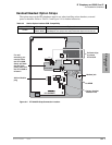
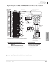
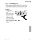
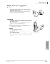
ISDN Interfaces
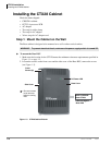
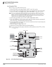
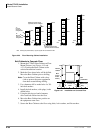
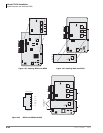
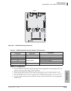
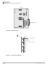
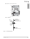
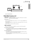
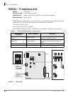
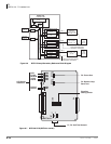
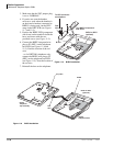
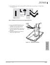
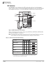
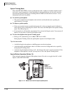
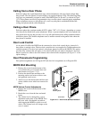
RBUU/RBUS Interface Unit
7-30 Strata CTX I&M 06/04
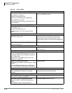
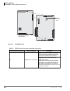
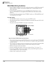
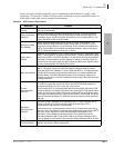
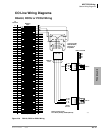
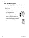
RBUU/RBUS Wiring Guidelines
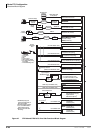
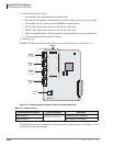
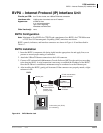
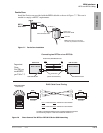
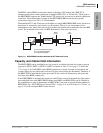
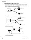
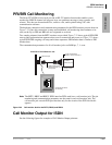
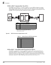
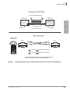
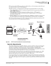
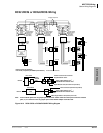
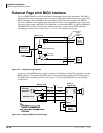
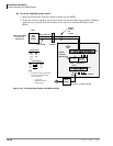
• Strata CTX BRI-U interface circuits can be configured to connect to an ISDN line circuit (NT
mode, line-side) or to ISDN U-type terminal equipment TE1 or terminal adapters TA (LT
mode, station side).
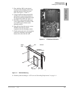
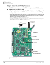
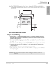
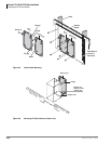
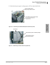
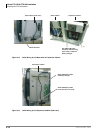
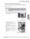
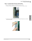
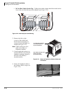
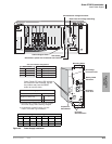
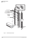
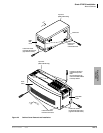
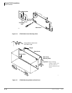
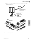
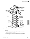
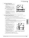
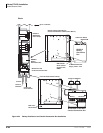
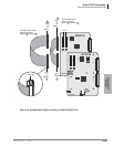
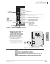
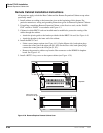
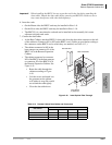
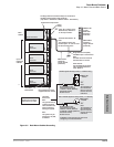
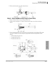
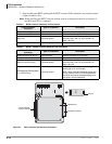
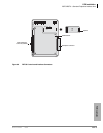
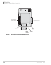
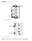
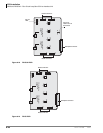
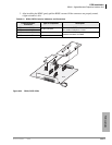
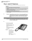
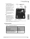
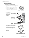
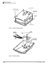
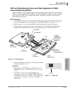
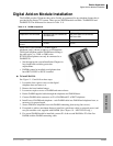
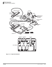
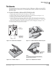
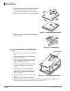
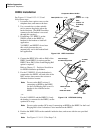
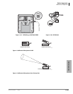
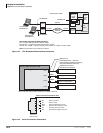
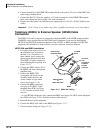
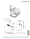
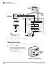
• Install the Toshiba-supplied Ferrite core on each ISDN circuit card per Figure 7-16 on
page 7-23. The Ferrite core is not supplied with the ISDN circuit cards must be ordered
separately.
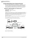
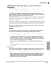
• For more information regarding the Strata CTX BRI-U interface, see “PRI and BRI Overview”
at the beginning of this chapter.
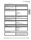
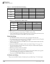
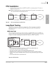
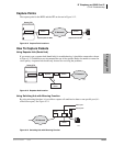
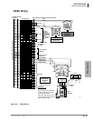
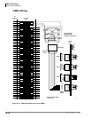
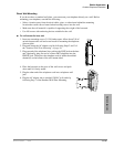
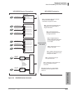
Line-side cabling
• The ISDN BRI U-interface circuits are two-wire on the PSTN line-side.
• The wiring from the demarc to the Strata CTX BRI circuit should be made with CAT3~CAT5
twisted pair wire.
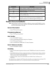
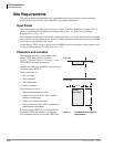
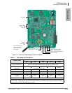
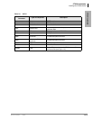
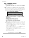
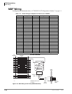
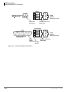
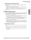
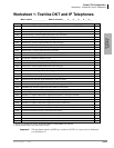
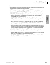
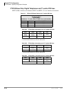
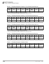
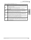
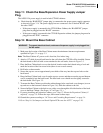
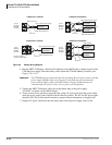
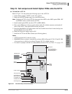
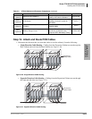
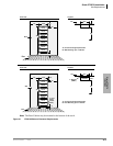
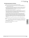
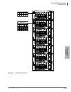
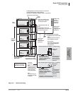
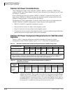
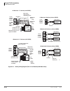
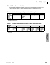
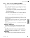
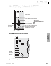
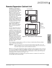
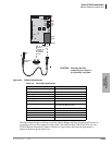
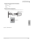
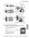
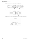
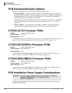
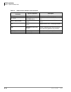
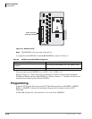
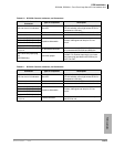
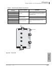
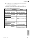
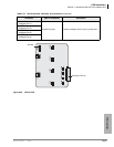
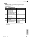
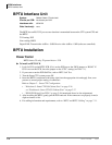
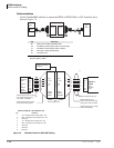
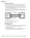
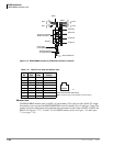
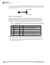
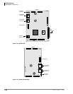
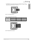
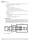
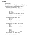
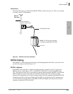
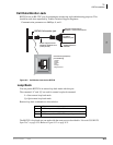
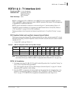
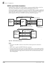
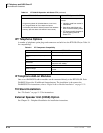
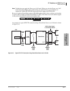
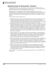
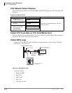
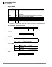
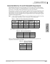
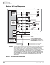
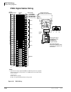
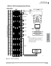
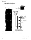
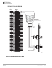
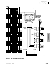
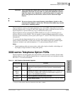
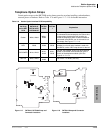
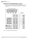
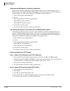
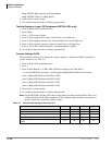
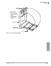
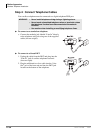
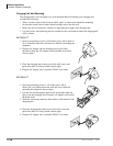
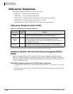
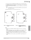
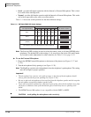
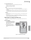
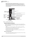
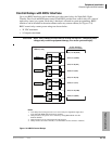
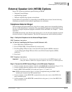
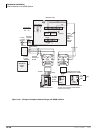
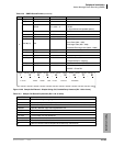
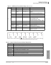
• The pinout of the Strata CTX BRI-U circuit jack is shown below.
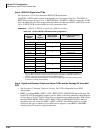
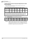
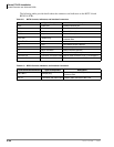
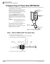
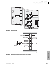
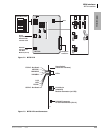
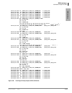
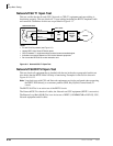
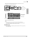
Figure 7-26 Strata CTX BRI-U RJ45 Circuit Jack Printout
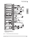
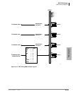
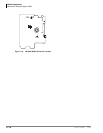
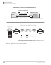
• The maximum distance between the PSTN BRI interface circuit and the Strata CTX ISDN BRI
U line-side circuit (NT) is 18 kft. The Telco with the use of a repeater or fiber optic cable may
extend this distance.
• The U interface pair should go directly from the demarc jack to the Strata CTX interface PCB
with no bridge taps to different locations or should not have loading coils installed.
• BRI line-side cables should not be shielded.
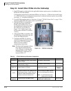
• Each line-side BRI circuit requires a ferrite core as shown in Figure 7-16 on page 7-23.
• In the USA, most BRI-U Demarc jacks are RJ11, but they may be RJ45 eight-wire jacks. In
Canada the BRI-U Demarc jack is usually RJ45.
• Polarity of the U interface pair is not critical.
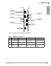
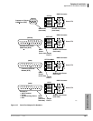
RJ45 Jack
NT and LT Mode
4732
8
7
6
5
4
3
2
1
NC
NC
NC
Tip
Ring
NC
NC
NC
NC = No Connection
BRI Pair