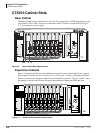
Strata CTX670 Installation
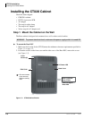
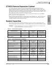
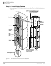
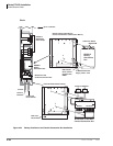
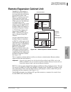
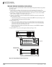
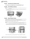
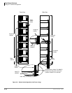
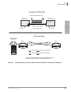
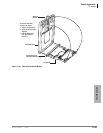
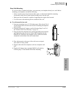
Remote Expansion Cabinet Unit
4-58 Strata CTX I&M 06/04
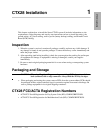
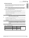
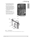
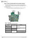
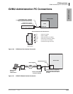
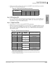
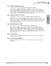
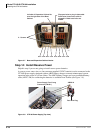
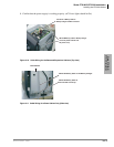
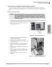
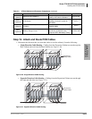
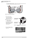
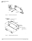
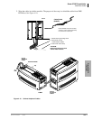
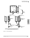
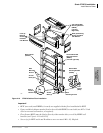
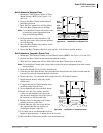
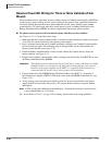
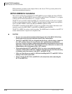
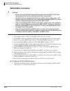
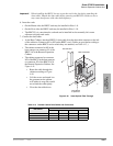
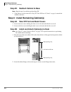
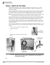
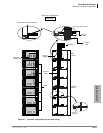
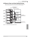
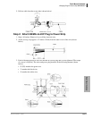
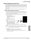
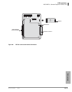
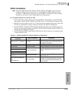
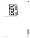
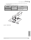
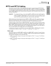
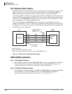
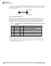
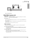
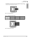
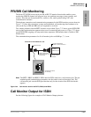
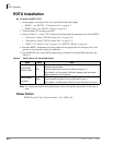
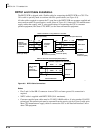
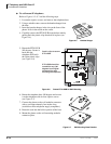
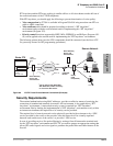
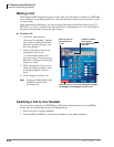
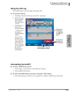
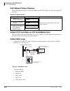
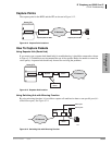
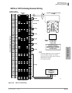
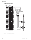
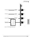
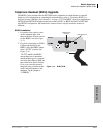
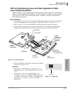
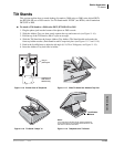
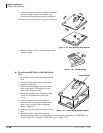
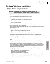
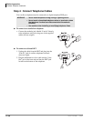
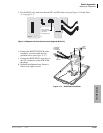
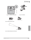
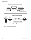
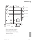
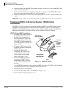
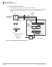
8. Connect the fiber optic cables
• Pass the fiber optic cable through the protective tube.
• Route the tube through the clamp attached to the inner cabinet wall and secure the clamp
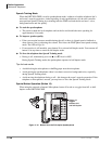
• Attach fiber to the SC connectors on the ROMS1A daughterboard.
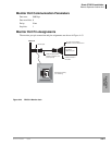
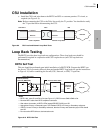
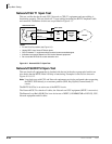
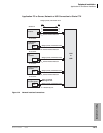
• The TX side of the Master connects to the RX side of the slave.
• The RX side of the Master connects to the TX side of the slave.
• TAIS recommends that the cables be marked within the cabinet for ease of maintenance.
• Observe the minimum bend radius of 30mm.
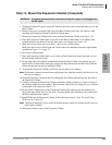
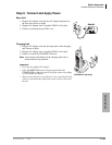
9. Restore power.
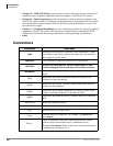
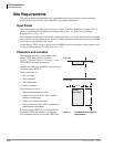
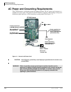
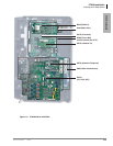
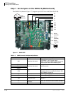
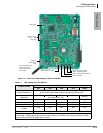
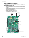
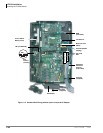
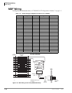
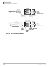
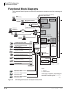
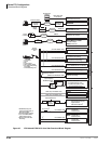
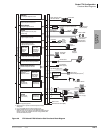
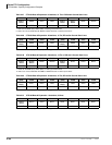
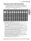
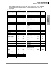
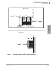
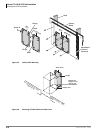
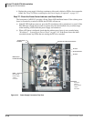
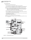
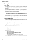
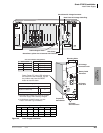
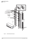
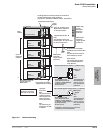
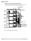
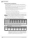
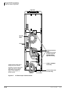
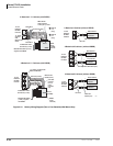
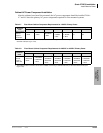
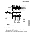
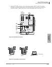
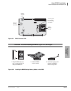
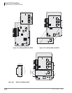
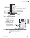
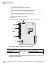
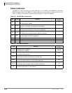
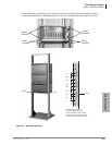
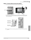
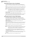
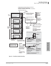
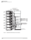
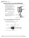
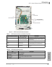
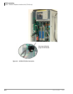
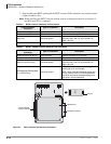
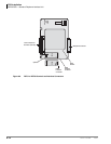
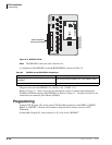
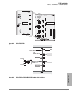
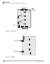
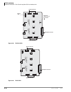
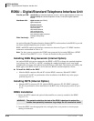
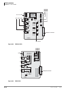
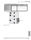
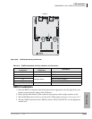
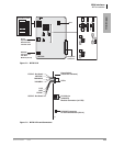
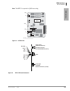
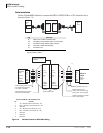
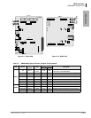
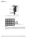
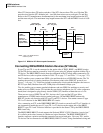
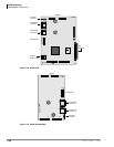
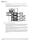
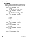
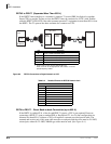
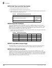
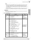
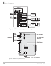
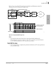
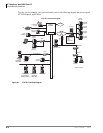
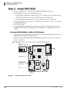
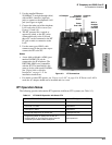
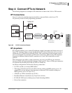
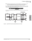
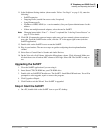
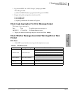
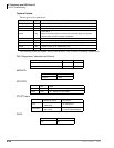
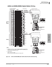
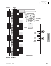
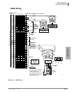
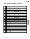
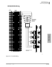
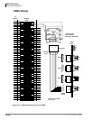
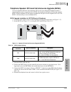
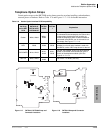
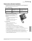
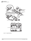
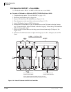
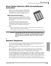
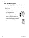
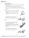
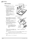
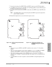
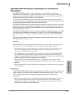
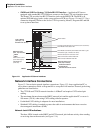
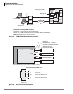
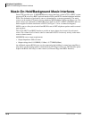
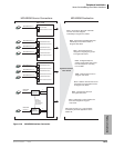
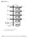
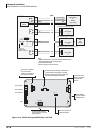
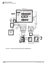
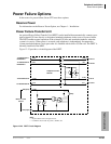
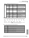
The RRCU PCB and its controls and connectors are shown in Figure 4-41 and Table 4-14.
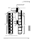
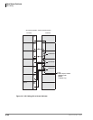
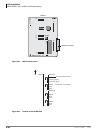
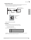
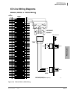
Figure 4-41 Remote Expansion Cabinet Printed Circuit Board (RRCU1A)
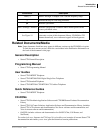
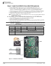
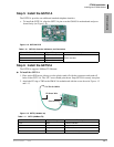
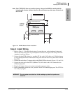
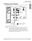
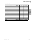
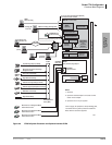
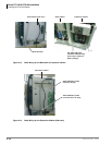
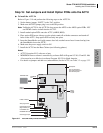
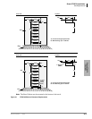
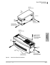
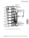
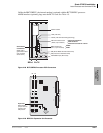
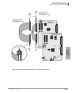
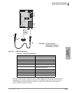
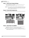
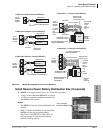
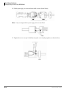
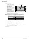
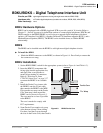
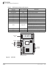
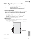
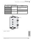
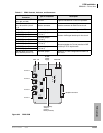
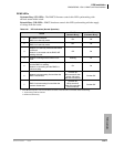
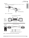
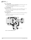
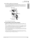
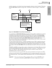
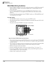
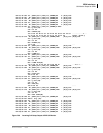
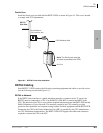
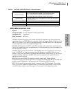
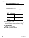
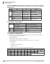
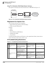
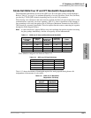
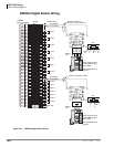
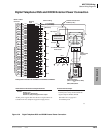
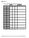
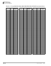
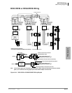
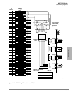
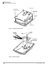
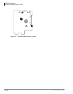
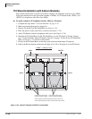
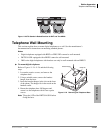
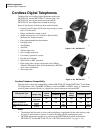
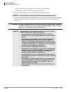
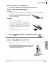
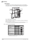
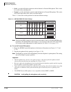
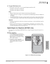
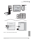
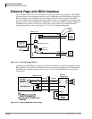
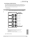
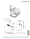
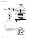
The ROMS subassembly and fiber optic cable connectors is shown in Figure 4-42. Table 4-15 lists
the fiber optic cable specifications.
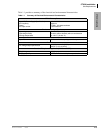
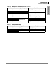
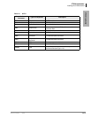
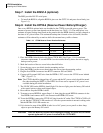
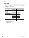
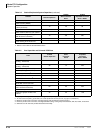
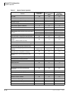
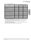
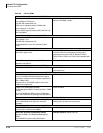
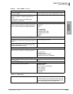
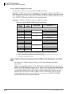
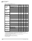
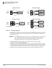
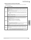
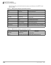
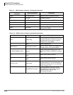
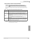
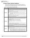
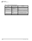
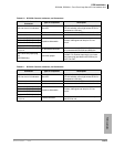
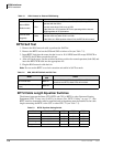
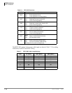
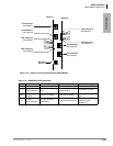
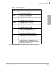
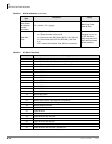
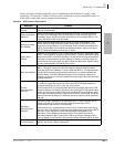
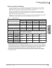
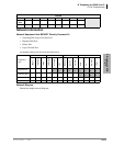
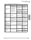
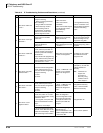
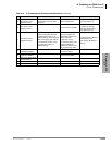
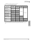
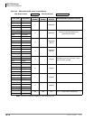
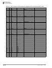
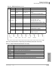
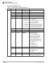
Table 4-14 RRCU Controls
Control/Indicator/Connector Type of Component Description
Jumper Plug P10
3-terminal Jumper Plug
Master Mode (M connections)
Jumper Plug P10 Slave Mode (S connections)
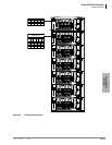
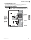
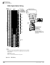
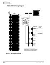
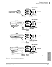
4356
RRCU1A
Backplane Connector
P8 P9P7P6
M2 S2S1M1
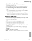
Master 1
Connect to
Base Cabinet
Master 2
Connect to
Base Cabinet
Slave 1
Connect
to MSBU
Slave 2
Connect
to MSBU
RS-232
Port
ROMS1A
MS
MS
P11
P10
P4
P3
P2P1