


INSTALLATION
6
YORK INTERNATIONAL
FORM 115.20-NOM2 (105)
7
YORK INTERNATIONAL
INSTALLATION
FORM 115.20-NOM2 (105)
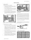
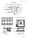
VALVE CLUSTER
2-Way Motorized Valve Assemblies
1. The motorized valve assembly should be attached to
the supply header, which is the connection nearest
the air outlet ange on the unit.
2. Prior to soldering the joints, operate all the hand
valves to ensure that the handles will fully open and
close without interference to other valves, ceiling,
wall, plenum or other accessories.
3. All valves will operate at any angle with the excep-
tion of the motorized valve, which must be installed
with the power head above horizontal. The actuator
box requires a 3/4" clearance for removal.
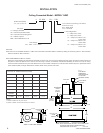
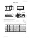
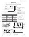
3-Way Motorized Valve Assembly
1. The 3-way valve assemblies will mount to the
coil in only one position. On four-pipe right hand
systems, a "B" valve assembly is required for the
chilled water connection and an "A" valve assembly
is required for the hot water connection. On left
hand systems, an "A" valve assembly is required
for the chilled water connection and the hot water
connection. (See gure 4.)
2. Prior to soldering the joints, operate all the hand
valves to ensure that the handles will fully open and
close without interference to other valves, ceiling,
wall, plenum or other accessories.
3. All valves will operate at any angle with the excep-
tion of the motorized valve, which must be installed
with the power head above horizontal. The actuator
box requires a 3/4" clearance for removal.
FIG. 5 – 3 WAY MOTORIZED VALVE ASSEMBLY
00187VIP
FIG. 4 – 2 WAY MOTORIZED VALVE ASSEMBLY
00186VIP
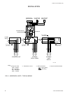
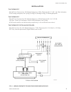
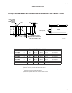
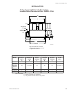
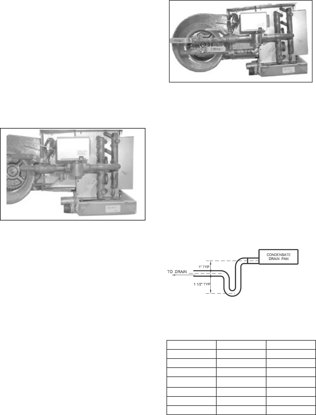
DRAIN PIPING
Condensate drain lines must be installed with adequate
slope away from the unit to assure positive drainage.
YRHBC and YCHBC fan coil units require a minimum
trap of 1-1/2 inches be provided in the drain line to
assure proper drainage. YHBC, YPHBC, YHH, YPHH,
YHYB, and YPHYB fan coil units may be located where
the return air space is large enough that a negative
pressure is not present, however, a trapped condensate
line is recommended to ensure proper drainage of unit in
case a negative condition should occur (see Installation
Drawings for locations and sizes).
The drain should always be connected or piped to an
acceptable disposal point sloped away from the unit at
least 1/8" per foot
LD04801
FIG. 6 – TYPICAL CONDENSATE PIPING
UNIT PRIMARY SECONDARY
YHBC 3/4 MPT 5/8 OD
YPHBC 3/4 MPT 3/4 MPT
YRHBC 3/4 MPT 3/4 MPT
YHH 3/4 MPT 7/8 OD
YPHH 3/4 MPT 7/8 OD
YHYB 3/4 MPT 3/4 MPT
YPHYB 3/4 MPT 3/4 MPT
TABLE 2 - DRAIN LINE SIZES