


INSTALLATION
6
YORK INTERNATIONAL
FORM 115.20-NOM2 (105)
7
YORK INTERNATIONAL
INSTALLATION
FORM 115.20-NOM2 (105)
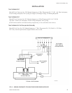
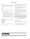
Prior to connecting to the fan coil,
all external piping must be purged
of debris.
When connecting piping or valve
kits to fan coil units, do not bend or
reposition the coil header tubing for
alignment purposes. This could cause
a tubing fracture resulting in a water
leak when water pressure is applied
to the system.
Many valve packages will not phys-
ically allow all components to fit
over an auxiliary drain pan. It is the
installers responsibility to ensure ad-
equate condensation prevention. The
installer must also ensure that there
is no condensate drippage onto elec-
trical components beneath insulated
components.
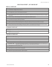
PRECAUTIONS
1. Flush all eld piping prior to connection to remove
all debris.
2. Use wet cotton rags to cool valve bodies when
soldering.
3. Open all valves (mid-way for hand valves, manually
open on motorized valves) prior to soldering.
4. When soldering to bronze or brass, heat the pip-
ing while in the socket/cup and begin introducing
the solder when the ux boils rapidly. Avoid direct
ame into the solder joint.
5. Heat can only be applied to the cup of the valve body
for a minimal time before damage occurs (even with
the use of wet rags.
6. Avoid rapid quenching of solder joints, as this will
produce joints of inferior quality.
7. The valve package will not support the weight of
the connecting pipes. All pipes, which are connected
to the units, must be completely supported prior to
connection to the unit.
8. Provisions must be made for expansion and con-
traction of piping systems. All horizontal and
vertical risers, including runouts, must be able to
withstand signicant movement with temperature
changes. Failure to do so will result in damage and
failure of piping, ttings and valves throughout the
building.
9. Never insulate the heads or motorized portion of
control valves. Damage can occur in the form of
excessive heat build up and interference to the
operation and moving parts will result.
10. All piping made in the eld should be installed with
consideration of additional space for any electrical
routing that may be required.
11. Hydronic systems are not designed to hold pres-
surized air and should only be tested with water.
After the system has been proven leak free, all lines and
valve control packages must be insulated as specied
on the building plans.
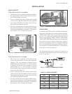
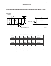
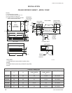
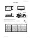
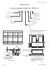
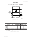
These units are provided with six (6) mounting holes
(see drawings for details). Metal washers and nuts of
the proper size are to be provided by the installer. When
necessary, use shims to obtain the proper level. This will
ensure that the condensate will drain from the unit.
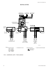
PIPING
These units employ a hydronic coil designed for use
with either hot or chilled water.
All piping must be adequately sized to meet the design
water ow requirements as specied for the specic
installation. Piping must be installed in accordance with
all applicable codes.
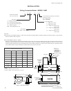
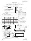
PIPE SIZES
All models except YHYB/YPHYB:
• HW/CW coils are 3/8" OD tubing.
• Tubing connections are 5/8" OD.
Models YHYB/YPHYB:
• HW/CW coils are 1/2" OD tubing.
• Tubing connections are 7/8" OD.
Manual air vents are provided standard on all coils
All chilled water piping must be insulated to prevent
condensation.