Johnson Controls Unitary Products 7
277805-YTG-A-1106
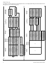
APPLYING FILTER PRESSURE DROP TO
DETERMINE SYSTEM AIRFLOW
To determine the approximate airflow of the unit with a filter in
place, follow the steps below:
1. Select the filter type.
2. Select the number of return air openings or calculate the
return opening size in square inches to determine the
proper filter pressure drop.
3. Determine the External System Static Pressure (ESP)
without the filter.
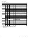
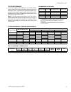
4. Select a filter pressure drop from the table based upon
the number of return air openings or return air opening
size and add to the ESP from Step 3 to determine the
total system static.
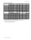
5. If total system static matches a ESP value in the airflow
table (i.e. 0.20, 0.60, etc,) the system airflow corre-
sponds to the intersection of the ESP column and Model/
Blower Speed row.
6. If the total system static falls between ESP values in the
table (i.e. 0.58, 0.75, etc.), the static pressure may be
rounded to the nearest value in the table determining the
airflow using Step 5 or calculate the airflow by using the
following example.
Example: For a 120,000 Btuh furnace with 2 return openings
and operating on high speed blower, it is found that total sys-
tem static is 0.58" w.c. To determine the system airflow, com-
plete the following steps:
1. Obtain the airflow values at 0.50" & 0.60" ESP.
Airflow @ 0.50": 2285 CFM
Airflow @ 0.60": 2175 CFM
2. Subtract the airflow @ 0.50" from the airflow @ 0.60" to
obtain airflow difference.
2175 - 2285 = -110 CFM
3. Subtract the total system static from 0.50" and divide this
difference by the difference in ESP values in the table,
0.60" - 0.50", to obtain a percentage.
(0.58 - 0.50) / (0.60 - 0.50) = 0.8
4. Multiply percentage by airflow difference to obtain airflow
reduction.
(0.8) x (-110) = -88
5. Subtract airflow reduction value to airflow @ 0.50" to
obtain actual airflow @ 0.58" ESP.
2288 - 88 = 2197
ACCESSORIES
PROPANE (LP) CONVERSION KIT -
1NP0347 - All Models
This accessory conversion kit may be used to convert natural
gas units for propane (LP) operation. Conversions must be
made by qualified distributor or dealer personnel.
CONCENTRIC VENT TERMINATION -
1CT0302 (2")
1CT0303 (3")
For use through rooftop, sidewall. Allows combustion air to
enter and exhaust to exit through single common hole.
SIDEWALL VENT TERMINATION KIT -
1HT0901 (3”) and 1HT0902 (2”)
For use on sidewall, two-pipe installations only. Provides a
more attractive termination for locations where the terminal is
visible on the side of the home.
CONDENSATE NEUTRALIZER KIT - 1NK0301
Neutralizer cartridge has a 1/2" plastic tube fittings for instal-
lation in the drain line. Calcium carbonate refill media is also
available from the Source 1 Parts (p/n 026-30228-000).
EXTERNAL SIDE RETURN FILTER RACK -
1SF0101 - Fits all cabinet sizes
Attaches to side of furnace cabinet in side return applications.
Holds any 16x25x1 permanent or disposable filter.
SIDE RETURN FILTER -
1SR0302 - All Models
1SR0200 - All Models
BOTTOM RETURN FILTER -
1BR0114 or 1BR0214 - For 14-1/2” cabinets
1BR0117 or 1BR0217 - For 17-1/2” cabinets
1BR0121 or 1BR0221 - For 21” cabinets
1BR0124 or 1BR0224 - For 24-1/2” cabinets
INTERNAL FILTER WITH FIBER FILTER -
1HF0801 - All Models
HIGH ALTITUDE PRESSURE SWITCHES -
For installation where the altitude is less than 8,000 feet it is
not required that the pressure switch be changed. For alti-
tudes above 8,000 feet see kits below. Conversion must be
made by qualified distributor or dealer personnel.
1PS0307 - 080, 100 MBH
1PS0309 - 060, 120 MBH
1PS0322 - 040, 135 MBH
ROOM THERMOSTATS - A wide selection of compatible
thermosets are available to provide optimum performance
and features for any installation.
1H/1C, manual change-over electronic non-programmable
thermostat.
1H/1C, auto/manual changeover, electronic programmable,
deluxe 7-day, thermostat.
1H/1C, auto/manual changeover, electronic programmable.
* For the most current accessory information, refer to the
price book or consult factory.