


172988-YUM-A-0106
Unitary Products Group 7
Hot Surface Ignition System
TROUBLESHOOTING
The following visual checks should be made before troubleshooting:
1. Check to see that the power to the furnace and the ignition control
module is ON.
2. The manual shut-off valves in the gas line to the furnace must be
open.
3. Make sure all wiring connections are secure.
4. Review the sequence of operation. Start the system by setting the
thermostat above the room temperature. Observe the system’s
response. Then use the troubleshooting section in this manual to
check the system’s operation.
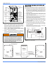
FURNACE CONTROL DIAGNOSTICS
This furnace has built-in self-diagnostic capability. If a system problem
occurs, a flashing LED shows a fault code. The LED can flash red,
green or amber to indicate various conditions. The LED is located on
the furnace control board and can be seen through the clear view port
in the lower door of the furnace. To indicate an error condition, the LED
will turn on for 1/4 second and off for 1/4 second. The pattern will be
repeated the number of times equal to the flash code. For instance, a
"six flash code" will be indicated by the LED turning on and off six times.
There will be a two second off period between each set of flashes. The
flash codes and an indication of their likely causes are listed below:
STEADY OFF - No 24V power to board. Check the 24 volt control cir-
cuit fuse on the board. Check the circuit breaker or fuse on the 115 volt
supply power to the furnace. Check that the 24 volt transformer.
One Green Flash - Normal Operation with no call for heat.
Two Green Flashes - Indicator for "No error codes in memory". See
Diagnostic Fault Code Storage and Retrieval section below.
Three Green Flashes - Indicator for "Error codes cleared from mem-
ory". See Diagnostic Fault Code Storage and Retrieval section below.
Rapid Green Flash - Control is in "Factory Speedup" mode. This mode
is used only during factory run-testing of the furnace. To stop this mode,
cycle power to the furnace off and then back on.
One Amber Flash - Normal operation with call for cooling.
Two Amber Flashes - Normal operation with call for heat.
Three Amber Flashes - Normal operation, burner is on at end of heat-
ing cycle after wall thermostat has been satisfied.
Four Amber Flashes - Heating capacity is reduced due to restriction in
the circulating air system.
Five Amber Flashes - Heating capacity is reduced due to restriction in
the combustion air or vent system.
Rapid Amber Flash - Low flame sense current. Check for dirty or mis-
located flame sensor rod.
One Red Flash - Flame is present with no power being supplied to gas
valve. This can be caused by a gas valve that is slow to close or that
leaks gas through to the burners.
Two Red Flashes - Stuck closed pressure switch. The control confirms
that the pressure switch contacts are open at the beginning of each
cycle. This could be caused by a faulty pressure switch or by mis-wiring
of the pressure switch.
Three Red Flashes - Stuck open pressure switch. This indicates that
the pressure switch is open when it should be closed. This could be
caused by a faulty combustion air blower, blocked vent pipe, blocked air
intake pipe, blocked condensate drain, faulty pressure switch hose or a
faulty pressure switch.
Four Red Flashes - High limit switch open or 24 volt fuse is open. This
may be caused by a dirty air filter, improperly sized duct system, faulty
blower motor, restricted circulating airflow or an open fuse on the con-
trol board.
Five Red Flashes - Rollout switch or auxiliary limit switch open. Check
the rollout switch on the side of the burner box. It is a manual reset
switch. To reset, push the small button in the center of the switch. If it
cannot be reset or if the switch trips again, contact a qualified service-
man. Check the limit switch mounted in the combustion air blower hous-
ing.
Six Red Flashes - Current failure on modulating gas valve.
Seven Red Flashes - Lockout due to no ignition. The control will try
three times for ignition. If flame cannot be established in three tries, the
control will lockout for one hour and then will try again to light. Check
gas supply, ignitor, gas valve, flame sensor.
Eight Red Flashes - Lockout due to too many flame recycles. This
flash code occurs if flame is lost five times during a single heating cycle.
This could be caused by a faulty gas valve, low gas pressure, or dirty
flame sensor. The control will lock out for one hour and then will try
again.
Nine Red Flashes - Reversed line polarity or improper grounding.
Check polarity of the incoming power to the furnace. Check the ground-
ing of the furnace, including the transformer ground and the L1 and
neutral connections.
Ten Red Flashes - Unexpected gas flow present. Check gas valve wir-
ing. If correct, replace gas valve.
Eleven Red Flashes - Main blower failure - This flash code occurs
when the main limit opens and fails to reclose within five minutes, indi-
cating that the blower motor or blower wheel has failed.
Twelve Red Flashes - ID plug is not present or not connected properly,
check for loose plug or loose wires in plug.
Steady On Red - Control fault has been detected or there is 24 volts
present without 115 volts. Check that there is 24 volts and 115 volts
being supplied to the board. If so, then the board should be replaced.
DIAGNOSTIC FAULT CODE STORAGE AND
RETRIEVAL
The control in this furnace is equipped with memory that will store up to
five error codes to allow a service technician to diagnose problems
more easily. This memory will be retained even is power to the furnace
is lost. Only a qualified service technician should use this feature.
The control stores up to five separate error codes. If more than five
error codes have occurred since the last reset, only the five most recent
will be retained. The furnace control board has a button, labeled "LAST
ERROR" that is used to retrieve error codes. This function will only
work if there are no active thermostat signals. So any call for heating,
cooling or continuous fan must be terminated before attempting to
retrieve error codes.
To retrieve the error codes, push the LAST ERROR button. The LED on
the control will then flash the error codes that are in memory, starting
with the most recent. There will be a two-second pause between each
flash code. After the error codes have all been displayed, the LED will
resume the normal slow green flash after a five second pause. To
repeat the series of error codes, push the button again.
If there are no error codes in memory, the LED will flash two green
flashes. To clear the memory, push the LAST ERROR button and hold it
for more than five seconds. The LED will flash three green flashes
when the memory has been cleared, then will resume the normal slow
green flash after a five-second pause.
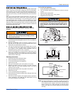
HOT SURFACE IGNITION SYSTEM
Do not attempt to light this furnace by hand (with a
match or any other means). There may be a potential
shock hazard from the components of the hot surface
ignition system. The furnace can only be lit automatically
by its hot surface ignition system.
Never bypass any safety control to allow furnace opera-
tion. To do so will allow furnace to operate under poten-
tially hazardous conditions.
Do not try to repair controls. Replace defective controls
with UPG Source 1 Parts.
Never adjust pressure switch to allow furnace operation.