


172988-YUM-A-0106
Unitary Products Group 5
If, during the inspection of your furnace, you find any of the following
conditions:
• Excessive amounts of dust and lint on components.
• Damaged or deteriorated components or surfaces.
• Leaks or blockage in the vent pipe passages.
• Water on any surface inside or outside of the furnace.
Do not operate the furnace, call a certified dealer / servicing contractor
to check and / or clean your furnace, or for more information if you have
questions about the operation of your furnace.
If all components appear to be in good operating condition, replace the
front panels. Turn ON the gas and electrical power supplies to the fur-
nace, and set thermostat to the desired temperature.
Motor Lubrication
The motors in these furnaces are permanently lubricated, and do not
require periodic oiling.
SECTION II: SERVICE AND MAINTENANCE
MANUAL
SAFETY
The following safety rules must be followed when servicing the
furnace.
FURNACE MAINTENANCE
The furnace should be cleaned and adjusted by a certified dealer or
qualified service contractor once a year or before the start of every
heating season. The following items must be cleaned and serviced or
replaced if there are signs of deterioration.
1. The vent terminal screen (if applicable).
2. The furnace vent and combustion air intake passageways. Should
it be necessary to service the vent/air intake system, the manufac-
turer recommends this service be conducted by a qualified service
agency. The operation of this appliance requires the reassembly
and resealing of the vent/air intake system.
3. The furnace burners, ignitor and flame sensor.
4. The condensate collection and disposal system. If any disassem-
bly of components containing flue or vent gases is required, a
qualified service agency must perform the service.
FURNACE CLEANING
NOTE: The cleaning operations listed below must be performed
only by a qualified service agency.
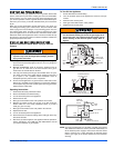
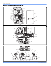
Burner Removal/Cleaning
The main burners should be checked periodically for dirt accumulation.
If cleaning is required, follow this procedure:
1. Turn off the electrical power to the unit.
2. Turn off the gas supply at the external manual shut-off valve and
loosen the ground union joint.
3. Remove the burner door and remove the burner box cover.
4. Disconnect wires from flame sensor, rollout switch and HSI igniter.
Remove igniter carefully, as it is easily broken.
5. Remove the screws that hold the burner box assembly to the vest
panel and remove the assembly.
6. Remove burners from the burner assembly.
7. Burners may be cleaned by rinsing in hot water.
8. Reassemble the burners in the reverse order.
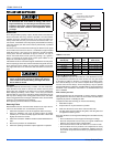
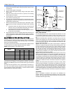
Cleaning the Heat Exchanger
1. Turn off the electrical power to the unit.
2. Turn off the gas supply at the external manual shut-off valve and
loosen the ground union joint.
3. Remove the burner door and remove the burner box cover.
4. Disconnect wires from flame sensor, rollout switch and HSI igniter.
Remove igniter carefully, as it is easily broken.
5. Remove the screws that hold the burner box assembly to the vest
panel and remove the assembly.
6. Remove the vent pipe assembly, vent blower and condensate pan.
7. The heat exchanger is now exposed.
8. With a long flexible wire brush, clean inside each tube at both the
top and bottom. The brush must pass around the rear heat
exchanger tubes. Then vacuum loose the scale and dirt from each
tube.
9. Replace all components in reverse order. Reconnect all wiring.
10. Restore electrical power and gas supply to the furnace.
11. Check furnace operation.
Cleaning the Secondary Heat Exchanger
1. Follow steps 1 - 7 under cleaning the Heat Exchanger.
2. Remove the vent piping from the vent blower housing. Disconnect
the drain lines from the vent blower housing and from the conden-
sate drain pan. Remove the vent blower housing blower and the
condensate pan.
3. Using a stiff wire brush, remove the loose scale or soot from each
tube.
4. Vacuum the secondary heat exchanger.
5. Finish the cleaning procedure by following steps 9 - 11 under
cleaning the Heat Exchanger.
Cleaning the Vent / Air Intake System
Should it be necessary to service the vent / air intake system, the man-
ufacturer recommends this service be conducted by a qualified service
agency.
The operation of this appliance requires the reassembly and resealing
of the vent / air intake system as specified in the “Combustion Air and
Vent System” located in the Installation Manual.
NORMAL OPERATION SEQUENCE
The furnace control calculates the optimum firing rate each time the
wall thermostat R and W contacts close or open (at the beginning and
at the end of each call for heat) based on information from the thermo-
stat and past demand. UNLIKE CONVENTIONAL SYSTEMS, THE
WALL THERMOSTAT DOES NOT SIMPLY TURN THE FURNACE ON
AND OFF. THE FURNACE CONTROL CALCULATES THE DEMAND
AND MAY CONTINUE TO FIRE THE FURNACE DURING PORTIONS
OF THE THERMOSTAT "OFF" CYCLE.
When the wall thermostat R and W contacts close, indicating a call for
heat, the following sequence occurs:
ELECTRIC SHOCK, FIRE OR EXPLOSION HAZARD
Failure to follow safety warnings exactly could result in
dangerous operation, serious injury, death or property
damage.
Improper servicing could result in dangerous operation,
serious injury, and death or property damage.
• Before servicing, disconnect all electrical power to the fur-
nace.
• When servicing controls, label all wires prior to discon-
necting. Reconnect wires correctly.
• Verify proper operation after servicing.
Label all wires prior to disconnection when servicing
controls. Wiring errors can cause improper and danger-
ous operation. Verify proper operation after servicing.