


172988-YUM-A-0106
6 Unitary Products Group
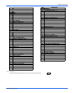
1. The inducer is energized and ramps up its speed until airflow is
proven by the pressure switch and by the pressure sensor on the
control board.
2. The hot surface ignitor is energized.
3. After a 17-20 second igniter heatup, the gas valve opens and the
burners light.
4. When the control senses that flame is present, the circulating
blower starts at low speed.
5. The furnace fires at 70% of full rate for 30-45 seconds, then drops
to the minimum (35%) firing rate.
6. The firing rate is automatically adjusted to meet demand, increas-
ing gradually to maximum (100%) firing rate if the thermostat is not
satisfied within a defined time.
7. When the thermostat R and W contacts open (thermostat is satis-
fied) the furnace control recalculates the demand and a new firing
rate.
a. If demand exceeds the minimum firing rate, the burners will
continue to fire at a recalculated reduced firing rate, decreas-
ing if the thermostat remains off for a defined time.
b. If demand does not exceed the minimum firing rate, the burn-
ers will shut off immediately.
8. After the burners shut off, the circulating blower will continue to run
until the temperature sensor detects that the supply air tempera-
ture has dropped to the desired level, which should take from 30 to
90 seconds.
ADJUSTMENT OF FAN CONTROL SETTINGS
Cooling - The airflow delivered by the furnace during cooling operation
can be adjusted to match the cooling capacity of the A/C condensing
unit. This is done by moving the COOL and ADJ jumper on the control
board to give the desired airflow.
The COOL jumper has four positions, which will deliver sufficient airflow
in cooling mode for the cooling capacities shown in the Table 2.
Continuous Fan Operation - The airflow delivered by the furnace dur-
ing continuous fan operation can be adjusted as desired. This is done
my moving the RECIRC jumper on the control board to give the desired
airflow.
The jumper has three positions. The "A" position delivers maximum air-
flow, 100% of the blower capacity. Position "B" delivers approximately
70% of the blower capacity. And Position "C" delivers minimum airflow,
approximately 35% of the blower capacity.
Delay Taps Selection
The set of jumper pins on the control board labeled "DELAY" are used
to set the delay profiles for the furnace. These can be chosen so as to
maximize the comfort and sound levels for various regions of the coun-
try.
Tap A is the default profile. It provides a 30-second ramp-up from zero
airflow to full capacity and a 30-second ramp-down from full capacity
back to zero airflow. Whenever there is a change in airflow mode, such
as from low heat to high heat, the motor will take 30 seconds to ramp
from one speed to the other.
Tap B is the humid profile. This profile is best-suited for installations
where the humidity is frequently very high during cooling season, such
as in the southern part of the country. On a call for cooling, the blower
will ramp up to 50% of full capacity and will stay there for two minutes,
then will ramp up to 82% of full capacity and will stay there for five min-
utes, and then will ramp up to full capacity, where it will stay until the
wall thermostat is satisfied. In every case, it will take the motor 30 sec-
onds to ramp from one speed to another.
Tap C is the dry profile. This profile is best suited to parts of the country
where excessive humidity is not generally a problem, where the sum-
mer months are usually dry. On a call for cooling the motor will ramp up
to full capacity and will stay there until the thermostat is satisfied. At the
end of the cooling cycle, the blower will ramp down to 50% of full capac-
ity where it will stay for 60 seconds. Then it will ramp down to zero. In
every case, it will take the motor 30 seconds to ramp from one speed to
another.
Tap D is the normal profile, best suited for most of the country, where
neither excessive humidity nor extremely dry conditions are the norm.
On a call for cooling, the motor will ramp up to 63% of full capacity and
will stay there for 90 seconds, then will ramp up to full capacity. At the
end of the cooling cycle, the motor will ramp down to 63% of full capac-
ity and will stay there for 30 seconds, then will ramp down to zero. In
every case, it will take the motor 30 seconds to ramp from one speed to
another.
Humidistat
When a humidistat is installed in the system, the “Humidistat con-
nected?” jumper on the control board should be moved to the “YES”
position. The cooling airflow will then be reduced by 15% whenever the
humidistat indicates high humidity.
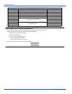
TABLE 2:
Cooling Airflow - A/C Capacity in Tons
Models
Cool Jumper Position
DCBA
60/1200 1-1/2 2 2-1/2 3
80/1200 1-1/2 2 2-1/2 3
80/1600 2-1/2 3 3-1/2 4
100/1600 2-1/2 3 3-1/2 4
100/2000 3 3-1/2 4 5
120/2000 3 3-1/2 4 5
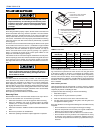
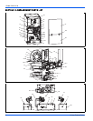
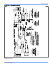
FIGURE 8: Furnace Control Board
LOW VOLTAGE
TERMINALS
DIAGNOSTIC
LIGHT
TEST
BUTTON
ERROR
BUTTON
CONTINUOUS FAN
SPEED JUMPER
COOLING
SPEED JUMPER
HUMIDIFIER
TERMINALS
EAC
TERMINALS
DELAY
COOL
ADJUST
R
W
Y/Y2
Y1
HUM
G
C
HUMIDISTAT
CONNECTED
YES
NO
AIR
RECIRC
ERROR
TEST
CFM
CFM
INDICATOR
ADJUST
JUMPER
DELAY
JUMPER