


246819-BTG-H-0208
Unitary Products Group 17
ACCESSORIES
Refer to Price Manual for specific model numbers.
Start Assist Kit (2SA067*)
Blower Time Delay - Available to increase efficiency when
installed. Installs on indoor section and maintains blower for
approximately one minute after cooling thermostat has been
satisfied.
Hard Start Kits - Provides required starting torque for use
with Thermal Expansion Valve Kit.
Low Temperature Cutout (2LT06700224) - Prevents heat
pump operation below -10°F ambient temperature.
Compressor Blanket - Designed to further reduce the nor-
mal operating sound.
Add-on Fossil Fuel Control - Interface controls for use with
gas, oil furnaces and the heat pump system are available.
Thermal Expansion Valve Kit - 1TVM700 Series TXV kit
used to improve system performance.
Outdoor Thermostat (2TD06700124) - Provides additional
staging of supplemental electric heat.
Room Thermostats - A wide selection of matching thermo-
stats is available to provide features required for any installa-
tion.
2H/1C, manual changeover electronic non-programmable
thermostat.
3H/2C, non-programmable digital thermostat.
3H/2C, auto/manual changeover, electronic programmable,
7-day, hardwire thermostat.
* For the most current accessory information, refer to the
price book or consult factory.
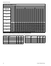
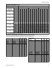
SOUND POWER RATINGS
* Rated in accordance with ARI 270-95 Standards.
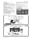
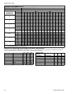
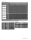
INSTALLATION CLEARANCES
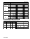
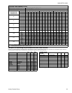
TYPICAL FIELD WIRING
UNIT MODEL
(dBA)*
Cooling Heating
018 73 72
024 75 76
030 74 76
036 76 77
042 77 78
048 78 78
060 79 79
MINIMUM 18” SERVICE ACCESS
CLEARANCE ON ONE SIDE
60” OVERHEAD
CLEARANCE
10” CLEARANCE
COIL AREA
WEATHERPROOF
DISCONNECT
SWITCH
THERMOSTAT
TO FURNACE OR
AIR HANDLER
TERMINAL BLOCK
NEC CLASS 1 WIRING
NEC CLASS 2 WIRING
TO INDOOR COIL
SEAL OPENING(S) WITH
PERMAGUM OR EQUIVALENT
CONTROL ACCESS PANEL
NOTE: ALL OUTDOOR WIRING
MUST BE WEATHERPROOF.
THERMOSTAT INDOOR UNIT
DEFROST
CONTROL
1
FIELD
INSTALLED
JUMPER
DEHUMIDIFICATION CONTROL CONNECTION
(Humidistat* Jumper must be removed)
GND.
SCREW
CONTACTOR
T2
T1
L2
L1
M
R
L or X
Y
O
W
G
T
2
E
2
R
R
Y
Y
O
O
W2
W
W1
C
C
X/L
G
W1
BK
GND.
LUG
CIRCUIT
BREAKER***
POWER WIRING
24V CONTROL WIRING
(NEC CLASS 2)
JUMPER TERMINALS E AND W TOHEAT
ON FIRST STAGE DURING EMERGENCY HEAT.
TERMINAL NOT USED ON ALL THERMOSTATS.
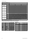
POWER WIRING
208/230-1-60
230-1-50
3
CHECK THE LOW VOLTAGE TERMINAL BLOCK ON THE INDOOR UNIT FOR THE ACTUAL ARRANGEMENT OF THE TERMINALS.
4
CONNECT POWER WIRING TO TERMINAL BLOCK 3TB ON UNITS WITHOUT ELECTRIC HEAT OR CIRCUIT BREAKER.
B or C
ALL FIELD WIRING TO BE IN ACCORDANCE WITH ELECTRIC CODE (NEC) AND/OR LOCAL CODE
S
RED
BLK
YEL
ORG
BRN
PUR
WHT
CC
GRY
/
66
5
GRAY FOR USE WITH OPTIONAL OUTDOOR THERMOSTAT KITS.
5