


3.Turnthe stem in (or clockwise) between 1/4 and 1/2 turn to
open the access port.
As soon as some internal pressure is relieved, close the ac-
cess port. DO NOT remove the entire holding charge.
NOTE: The copper disc on the liquid connection will prevent
any internal pressure from being relieved through the
main port of the liquid line stop valve.
If the unit has already lost its holding charge, it should be
leak tested and the necessary repairs should be made. If the
unit has maintained its holding charge, you can assume that
it has no leaks and proceed with the installation.
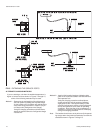
CAUTION: Dry nitrogen should always be supplied through a
connectionwhileitis beingbrazedorunbrazedbe
-
causethetemperaturerequired tomakeorbreaka
brazed joint is sufficiently high to cause oxidation
of the copper unless an inert atmosphere is pro
-
vided. The flow of nitrogen should be continued
until the joint has cooled.
WARNING The drynitrogen must always be supplied through
a pressure regulating valve.
Before installing the liquid line between the outdoor and in
-
door units, remove the copper disc from the liquid connection
on the outdoor unit per the following procedure:
1.Make sure the refrigerant in the line has been recovered
and that the liquid service valve on the unit is front-seated
and closed. The valve stem should be turned to its maxi
-
mum clockwise position.
2.Drillasmall holethrough thedisc beforeunbrazingit toper
-
mit a flow of dry nitrogen through the connection while it is
being unbrazed.
WARNING: This hole is also required to prevent the internal
pressure from building up as the disc is being un
-
brazed and from blowing the disc off.
This warning applies to any disc being removed
from a service valve, coil connection, etc.
3.Remove the capfrom the 1/4" access port onthe liquid line
stop valve.
4.Connect a supply of dry nitrogen to this access port.
5.Unbraze the copper disc from the liquid connection while
maintaining a minimum flow of dry nitrogen through the
connection.
After
the disc has been removed,
1.Burnish the external surfaces of the liquid connection on
the outdoorunit and the endof the field-supplied pipingbe-
ing used for the liquid line.
NOTE: Cleansurfaces areessential fora well brazedconnec-
tion.
2. Carefully clean theinternal surfaces of the above. Anypar-
ticles left on these surfaces may lead to a future system
malfunction.
NOTE: Use only copper tubing that has been especially
cleaned and dehydrated for refrigerant use. If the tub-
ing has been open for an extended period of time, it
should be cleaned before being used.
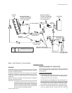
The liquid line connections can now be brazed while maintain
-
ing a minimum flow of dry nitrogen through the piping.
NOTE: A filter-drier is factory-mounted in the outdoor unit for
the heating cycle and in the indoor unit for the cooling
cycle.
Do NOT install another filter-drier in the field-supplied
liquid line because refrigerant will flow in both direc
-
tions on a heat pump system.
Recover theholding charge of theindoor unit andthen remove
the sealingcaps ordiscs fromboth itsliquid and vaporconnec
-
tions per the following procedure:
1. Make sure the refrigerant in the lines has been recovered,
then drill a small hole through both the liquid disc and the
vapor disc. If the holding charge has already been lost, the
coil should be leak-tested and the necessary repairs
should be made.
2. Move the dry nitrogen supply from the access port on the
liquid line service valve of the outdoor unit to the hole
through the vapor disc on the indoor unit.
3. Unbrazethe coil'sliquidline discwhilemaintaininga flowof
dry nitrogen across the connection and through the hole in
the liquid line disc.
8 Unitary Products Group
035-16192-001-A-1001
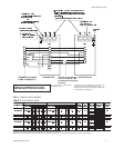
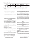
Refrigerant
Line
2
Line Size,
OD (In.)
Refrigerant Charge
(Lb/Ft)
Liquid 5/8 0.113
Vapor
1-1/8
0.013
1-3/8
1
Charges are based on 40°F suction temperature and 105°F liquid temperature.
2
Type “L” copper tubing.
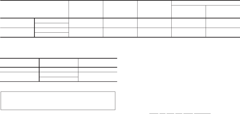
TABLE 6 - REFRIGERANT LINE CHARGE
1
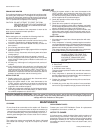
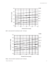
Use these line charges to adjust the system operating
charge when the refrigerant lines are more or less than the
25 feet listed in Table 2.
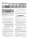
Model Designation
Nominal
Capacity
(Tons)
Refrigerant
Flow Rate
1
(Lbs./Min.)
Type L
Copper Tubing
(Inches O.D.)
Pressure Drop
3
Friction
2
(PSI/100 Ft.)
Vertical
Rise
(PSI/Ft.)
180
System 1
7-1/2 22.5 5/8 3.5 0.5
System 2
240
System 1
10 30.0 5/8 5.8 0.5
System 2
1
Based on Refrigerant-22 at the nominal capacity of the condensing unit, a liquid temperature of 105°F and a suction temperature of 40°F.
2
These friction losses do not include any allowances for a strainer, filter-drier, solenoid valve, isolation valve or fittings.
3
The total pressure drop of the liquid line for both friction and vertical rise must not exceed 40 PSI. If the pressure drop exceeds 40 PSI, the liquid refrigerant could flash before it reaches the
TABLE 5 - LIQUID LINES