


and/or drafts. Circulation of air to the thermostat should not
be blocked by curtains, drapes, furniture, partitions, etc.
Some installations may require a locking cover to protect the
thermostat from tampering and/or damage.
Both the manual and the auto changeover thermostats have
non-adjustable, voltage-type anticipators for both cooling and
heating.
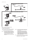
REFRIGERANT PIPING
GENERAL GUIDELINES
Many service problems can be avoided by taking adequate
precautions to provide an internally clean and dry system
and by using procedures and materials that conform with es-
tablished standards.
Use hard drawn copper tubing where no appreciable amount
of bending around pipes or other obstructions is necessary.
Use long radius ells wherever possible with one exception -
small radius ells for the traps in all vapor risers. If soft copper
is used, care should be taken to avoid sharp bends which
may cause a restriction.
Pack fiber glass insulation and a sealing material such as
permagum around refrigerant lines where they penetrate a
wall to reduce vibration and to retain some flexibility.
Support all refrigerant lines at minimum intervals with suitable
hangers, brackets or clamps.
Braze all copper to copper joints with Sil Fos-5 or equivalent
brazing material. Do not use soft solder.
Insulate all vapor lines with a minimum of 1/2" ARMA-FLEX or
equal. Liquid lines exposed to direct sunlight and/or high tem
-
peratures must also be insulated.
Neversolder vaporandliquidlines together.Theycanbe taped
together for convenience and support purposes, but they must
be completely insulated from each other.
LINE SIZING
When sizing refrigerant lines for a split-system air conditioner,
check the following:
1. Suction line pressure drop due to friction at full capacity,
2. Liquid line pressure drop due to friction at full capacity,
3. Suction line velocity for oil return at part capacity, and
4. Liquid line pressure drop due to static head.
NOTE: Never base refrigerantline sizes on the OD of thesuc
-
tion and liquid connections on the unit.
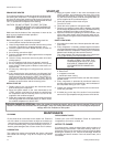
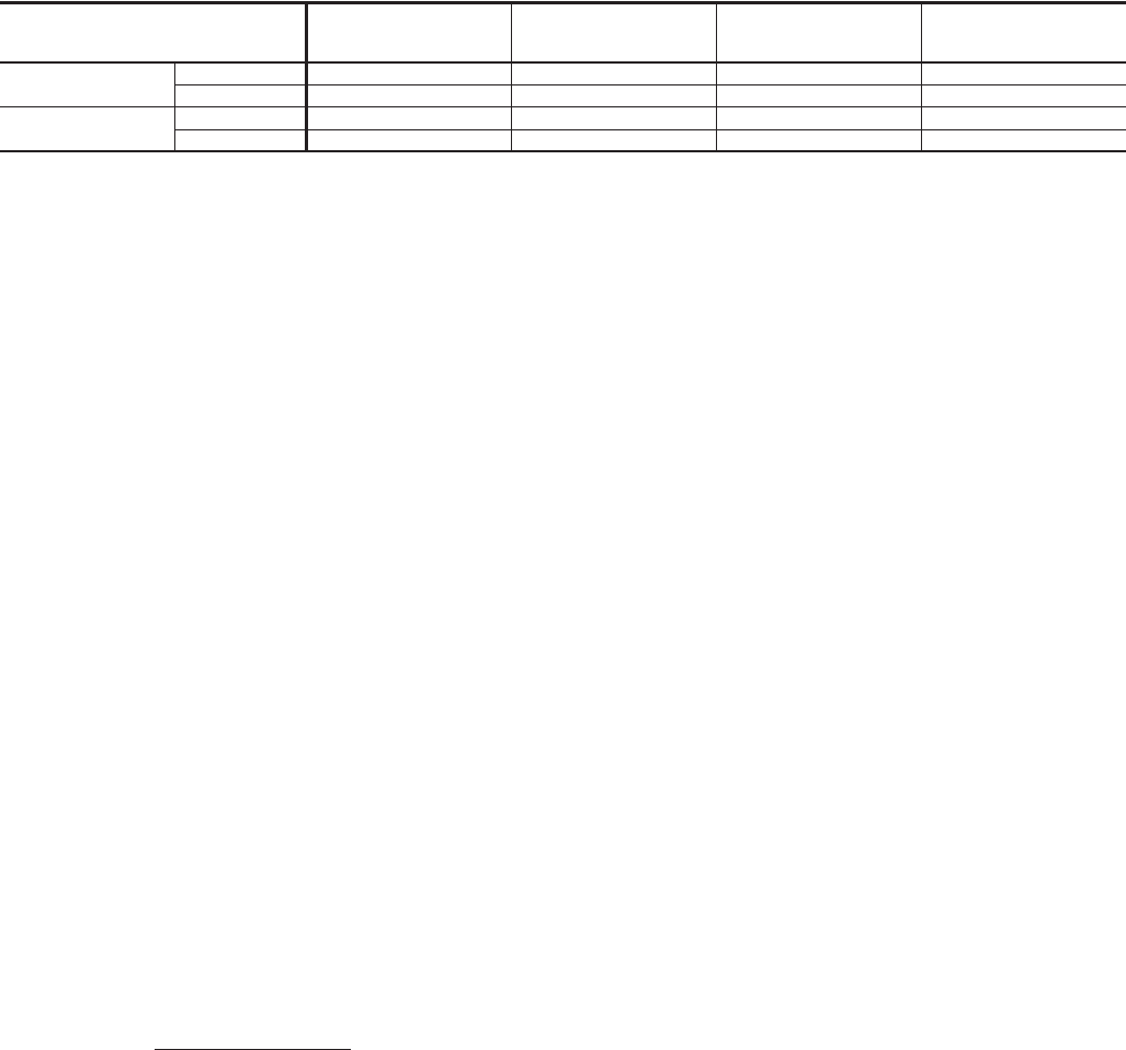
Tables 4 and 5 list friction losses for both the suction and liq
-
uid lines on the system. Table 6 shows the amount of refrig
-
erant charge required per foot of refrigerant line.
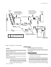
When the evaporator coil is below the condensing unit, the
suction line must be sized for both pressure drop and for oil
return. For certain piping arrangements, different suction line
sizes may have to be used. The velocity of the suction gas
must always be great enough to carry oil back to the compressor.
When the condensing unit is below the evaporator coil, the
liquid line must be designed for the pressure drop due to
both friction loss and vertical rise. If the total pressure drop
exceeds 40 psi, some refrigerant may flash before it reaches
the thermal expansion valve. This flashing will not only
cause erratic valve operation and poor system performance,
but could also damage the expansion valve.
SERVICE VALVES
These outdoor units have both vapor and liquid line service
valves.
Both valves are shipped from the factory front-seated and
closed with the valve stem in the maximum clockwise posi
-
tion.
These service valves are the back-seating type and have a
1/4" male flare access port for evacuating and charging the
system.
Shrader access valves are provided on the compressor va
-
por and discharge lines for pressure checking the system.
All access ports are sealed with a removable cap. Never re
-
move a cap unless the valve is fully back-seated with its
valve stem in the maximum counter-clockwise position be
-
cause the refrigerant charge will be lost.
INSTALLATION
Since these units are shipped with a holding charge of
Refrigerant-22, they can be checked for a refrigerant leak by
opening the access port on the liquid line service valve as fol
-
lows:
1.Openthevalve byturningthestemto itsmaximumcounter-
clockwise position.
2.Remove the cap from the access port.
WARNING: Provisions for recovering refrigerant releases
mustbe availableduring allphasesof installa
-
tion, leak testing and charging. Do NOT re
-
lease refrigerant into the atmosphere.
Unitary Products Group 7
035-16192-001-A-1001
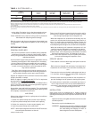
Model
Designation
Nominal
Capacity
(Tons)
Refrigerant
Flow Rate
3
(Lbs./Min.)
Type L
Copper Tubing
(Inches O.D.)
Friction
Loss
4,5
(PSI/100 Ft.)
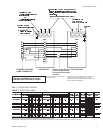
180
System 1 7-1/2 22.5 1-1/8 4.7
System 2 7-1/2 22.5 1-1/8 4.7
240
System 1 10 30 1-3/8 2.8
System 2 10 30 1-3/8 2.8
1
All horizontal suction lines should be pitched at least 1 inch every 20 feet in the direction of the refrigerant flow to aid the return of oil to the compressor.
2
Every vertical suction riser greater than 25 feet in height should have a “P” trap at the bottom to facilitate the return of oil to the compressor. Use short radius fittings for these traps.
3
Based on Refrigerant-22 at the nominal capacity of the condensing unit, a suction temperature of 40°F and a liquid temperature of 105°F.
4
Although suction lines should be sized for a friction loss equivalent to a 2°F change in saturation temperature (or approximately 3 psi), sizing the lines for the proper return of oil
is more important.
5
These friction losses do not include any allowances for valves or fittings.
6
Since the refrigerant gas velocity may be too low to maintain good oil return up a vertical riser, use the next smaller size. The larger size may be used for horizontal runs for a smaller
pressure drop.
TABLE 4 - SUCTION LINES
1,2