


GENERAL
During the cooling cycle, when the reversing valve solenoids
becomesenergized, operationwillbe thesameasany conven
-
tional air conditioning system.
During the heating cycle, when the reversing valve solenoids
becomes de-energized, compressor discharge gas will be di
-
verted to the indoor coil and the outdoor coil will become the
evaporator.
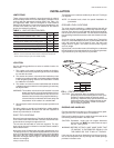
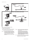
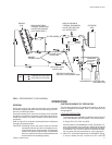
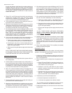
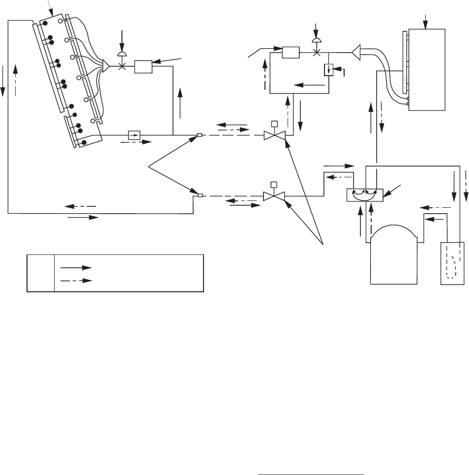
Refer to Figure 6 for illustration showing the flow of refrigerant
through a heat pump system.
CAUTION: Reversing valves and check valves are precise
mechanical devices and will not tolerate any me
-
chanicalabusesuchas hammering.Ifarefrigerant
system isn't properly cleaned after a compressor
burn-out, scale may build up at these devices and
prevent them from operating properly.
SYSTEM SEQUENCE OF OPERATION
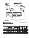
The following sequences of operation are based on using the
manual changeover thermostat. Refer to the respective unit
wiring diagram.
COOLING OPERATION
1.The following controlswill be energized throughterminal O
on the thermostat to put the system in the cooling mode.
•
Relays RY3, RY4, RY5, and RY6
2.Ifthe fanswitchon thethermostatis inthe“ON” position,in
-
door section blower motor contactor 10M will be energized
throughterminal Gto providecontinuousblower operation.
If the switch is in the “AUTO” position, the blower will oper
-
ate only when the thermostat calls for cooling operation.
3. When TC1of thethermostat closeson demand forcooling,
a circuit is made from the Y terminal on DC1 and DC2
Unitary Products Group 11
035-16192-001-A-1001
INDOOR
COIL
NON-ADJUSTABLE
THERMAL EXPANSION
VALVE FOR COOLING
(10°F SUPER HEAT)
FILTER DRIERS
NON-ADJUSTABLE
THERMAL EXPANSION
VALVE FOR HEATING
(5°F SUPER HEAT)
OUTDOOR
COIL
CHECK
VALVE
FIELD-INSTALLED
LIQUID LINE
FIELD-INSTALLED
VAPOR LINE
SERVICE VALVES WITH
COPPER STUB CONNECTIONS
REVERSING
VALVE WITH
24-VOLT
SOLENOID
COMPRESSOR SUCTION LINE
ACCUMULATO
R
BRAZED
CONNECTIONS
KEY
COOLING CYCLE FLOW
HEATING CYCLE FLOW
OPERATION
FIG. 6 - REFRIGERANT FLOW DIAGRAM