


246721-YTG-C-0606
Unitary Products Group 9
• Power Exhaust - This accessory installs in the unit with
a down flow economizer. Power exhaust plugs into the
connector in the unit bulkhead. You must purchase
1EH0408 barometric relief when applying to a hori-
zontal flow application.
• Manual Outdoor Air Damper - Like the motorized out-
door air damper, each manual outdoor air damper
includes a slide-in damper assembly with an outdoor air
hood and filters. Customers have a choice of dampers
with ranges of 0% to 100% or 0% to 35% outdoor air entry.
• Motorized Outdoor Air Damper - The motorized out-
door air damper includes a slide-in/plug-in damper
assembly with an outdoor air hood and filters. The out-
door air dampers open to the preset position when the
indoor fan motor is energized. The damper has a range
of 0% to 100% outdoor air entry. Factory installed option
or field installed accessory.
• Smoke Detectors - The smoke detectors stop operation
of the unit by interrupting power to the control board if
smoke is detected within the air compartment.
• CO
2
Sensor - Senses CO
2
levels and automatically
overrides the economizer when levels rise above the
preset limits.
• Dirty Filter Switch - This kit includes a differential pres-
sure switch that energizes the fault light on the unit ther-
mostat, indicating that there is an abnormally high
pressure drop across the filters.
• Coil Guard - Field installed decorative wire coil guard.
• Hail Guard - This kit includes a sloped hood which installs
over the outside condenser coil and prevents damage to
the coil fins from hail strikes. Field installed accessory only.
• Flue Exhaust Extension Kit - In locations with wind or
weather conditions which may interfere with proper
exhausting of furnace combustion products, this kit can
be installed to prevent the flue exhaust from entering
nearby fresh air intakes.
• -60°F Gas Heat Kit - For installations which require gas
heat units to perform in low ambient temperatures, a gas
section heating kit is available. This kit provides electric
heat in the gas heat controls section to ensure the gas
valve and controls will continue to function properly at
extremely low temperatures.
• Gas Heat High Altitude Kit - This kit converts a gas heat
unit to operate at high altitudes, 2,000 to 6,000 feet. Con-
version kits are available for natural gas and propane.
• Gas Heat Propane Conversion Kit - This kit converts a
gas-fired heater from natural gas to propane. It contains the
main burner orifices and gas valve replacement springs.
• Gas Piping Kit - Contains pipe nipples, fittings and gas
cock required for gas supply connection with external
shut off.
• Electric Heaters - The electric heaters range from 9 kW
to 54kW and are available in all the voltage options of the
base units. All heaters are dual staged. Cooling units
include an adapter panel for easy installation of the elec-
tric heaters. Necessary hardware and connectors are
included with the heaters. All heaters are intended for
single point power supply.
• Low Limit / Compressor Lockout Kit
1. Compressor Lockout (CLO): To prevent mechanical
(compressorized) operation of the unit during cold
outdoor conditions where there is a risk of returning
liquid refrigerant back to the compressors.
2. Low Limit Control (LLC): To prevent the supply air
from dropping below a specified setpoint by utilizing
the units first stage heating means when there is a
demand for cooling during cold outside conditions.
• Metal Frame Filter Kit - Metal frame with polyester filter
medium.
• Permanent Filters - Permanent filters are available.
• Roof Curbs - The roof curbs have insulated decks and
are shipped disassembled The roof curbs are available
in 8” and 14” heights. For applications with security con-
cerns, burglar bars are available for the duct openings of
the roof curbs.
• Roof Curb Transition - Single Piece Adapter (10” High) -
Roof curbs for transitioning from Sunline™ units to Pred-
ator
®
units. Fits 7.5 to 12.5 Sunline™
roof curbs only.
• Burglar Bars - Mount in the supply and return openings
to prevent entry into the duct work.
• Thermostat - The units are designed to operate with 24-
volt electronic and electro-mechanical thermostats. All
units (with or without an economizer) operate with two-
stage heat/two-stage cool or two-stage cooling only ther-
mostats, depending upon unit configuration.
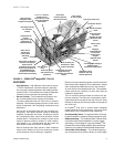
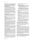
REHEAT MODE SEQUENCE OF OPERATION
The reheat control board allows the user to select two differ-
ent modes of operation via a jumper connection on the
board. (See Figure 3.) Each mode is described below. Refer
to Figures 3 - 5 when reading this section.
“NORMAL” MODE
When the reheat control board (RCB) detects a need for
dehumidification (24VAC) at "HUM" via the field supplied
dehumidistat connected to RHTB-1 and RHTB-2 and there is
not a call for cooling, it energizes the hot gas relay (HGR),
which energizes the 3-way valve (SOL 3), the condenser coil
valve (SOL 2), and de-energizes the reheat coil bleed valve
(SOL 1). (In the DR150, SOL 2 is only energized when the
discharge pressure in circuit #1 rises above 235 psig and de-
energizes SOL 2 after the discharge pressure falls below 175
psig. Both outdoor fans of circuit #1 in the DR150 also disen-
gage to conserve energy.) The Y1 signal is passed to the unit
control board (UCB), which engages circuit # 1, resulting in
circuit #1 reheat mode operation.
When the room thermostat calls for first stage cooling, with or
without a call for dehumidification, the RCB senses a signal
through "Y1", de-energizing the HGR, which de-energizes
SOL 3 and SOL 2 and energizes SOL 1, engaging circuit #1,
resulting in circuit #1 cooling mode operation.