


036-21366-007-A-1205
18 Unitary Products Group
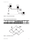
FIGURE 3 - FIELD WIRING DIAGRAM CONTROL WIRING
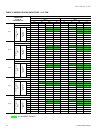
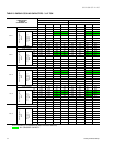
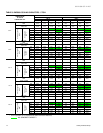
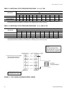
TABLE 12: ADDITIONAL STATIC PRESSURE RESISTANCE - 2, 2-1/2, 3 TON
DESCRIPTION
RESISTANCE, IWG
CFM
500 600 700 800 900 1,000 1,100 1,200 1,300 1,400 1,500 1,600
WET EVAPORATOR COIL .01 .01 .01 .02 .03 .04 .05 .06 .07 .08 .09 .09
ECONOMIZER
1
.00 .00 .00 .01 .01 .01 .01 .02 .03 .04 .05 .06
FILTER FRAME KIT .01 .02 .04 .06 .08 .10 .13 .16 .17 .18 .19 .20
1.
The pressure through the economizer is greater for 100% outdoor air than for 100% return air. If the resistance of the return air
duct system is less than 0.25 IWG, the unit will deliver less CFM during full economizer operation.
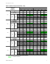
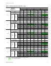
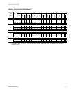
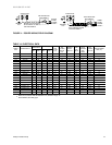
TABLE 13: ADDITIONAL STATIC PRESSURE RESISTANCE - 3-1/2, 4 AND 5 TON
DESCRIPTION
RESISTANCE, IWG
CFM
1,100 1,200 1,300 1,400 1,500 1,600 1,700 1,800 1,900 2,000
WET EVAPORATOR COIL .02 .03 .04 .05 .06 .07 .07 .08 .09 .09
ECONOMIZER
1
.02 .02 .02 .03 .03 .04 .04 .04 .05 .05
FILTER FRAME KIT .04 .04 .05 .05 .06 .07 .08 .09 .10 .11
1.
The pressure through the economizer is greater for 100% outdoor air than for 100% return air. If the resistance of the return air
duct system is less than 0.25 IWG, the unit will deliver less CFM during full economizer operation.
R
G
W
R
G
C
YY
W
C
PROGRAMMABLE
THERMOSTAT ONLY
**
*
*=Minimumwiresizeof18AWG
wire should be used for all
field installed 24 volt wire.
THERMOSTAT
UNIT TERMINAL STRIP
NOTE:
HEAT ANTICIPATOR
SHOULD BE SET AT 0.35
AMPS FOR ALL MODELS.
24 VOLT
TRANSFORMER