262259-YTG-B-0107
Unitary Products Group 5
with aluminized steel or optional stainless steel tubes, a
redundant gas valve, spark ignition, power venting, an
ignition module for 100% shut-off and all of the safety
controls required to meet the latest ANSI standards.
The gas supply piping can be routed into the heating
compartment through a hole in the base pan of the unit
or through a knockout in the piping panel on the front of
the unit.
• Electric Heat Operation - All electric heat models (fac-
tory installed only) are wired for a single power source
and include a bank of nickel chromium elements
mounted at the discharge of the supply air blower to pro-
vide a high velocity and uniform distribution of air across
the heating elements. Every element is fully protected
against excessive current and temperature by fuses and
two thermal limit switches.
The power supply wiring can be routed into the control
box through a threaded pipe connection in the base pan
of the unit or through a knockout in the wiring panel on
the front of the unit.
• BAS Controls - York’s Sunline™ series units offer factory
mounted BAS controls such as Simplicity® INTELLI-Com-
fort™, Novar, Honeywell, Johnson, and CPC.
FACTORY-INSTALLED OPTIONS
• SINGLE INPUT ELECTRONIC ENTHALPY ECONO-
MIZERS - Includes a slide-in / plug-in damper assembly
with fully modulating spring-return motor actuator capa-
ble of introducing up to 100% outdoor air with nominal
1% leakage type dampers.
The enthalpy system contains one sensor that monitors
the outdoor air and determines when the air is cool
enough and dry enough to provide free cooling.
The rainhood is painted to match the basic unit and must
be field-assembled before installing.
• POWER EXHAUST - Our single economizer options are
available with power exhaust. Whenever the outdoor air
intake dampers are opened for free cooling, the exhaust
fan will be energized to prevent the conditioned space
from being over-pressurized during economizer operation.
The exhaust fan, motor and controls are installed and
wired at the factory. The rain hood must be assembled
and installed in the field.
The power exhaust option can only be used on bot-
tom duct configurations.
• MOTORIZED OUTDOOR AIR INTAKE DAMPER -
Includes a slide-in / plug-in damper assembly with a 2-
position, spring return motor actuator which opens to a
pre-set position whenever the supply air blower is oper-
ating and will drive fully closed when the blower unit
shuts down.
The rain hood is painted to match the basic unit and
must be field assembled before installing.
• PHENOLIC COATED EVAPORATOR AND CON-
DENSER COILS - Special coating process that utilizes
Technicoat 10-1" processes. Coating is applied by total
immersion of the complete coil for maximum protection.
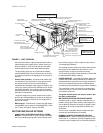
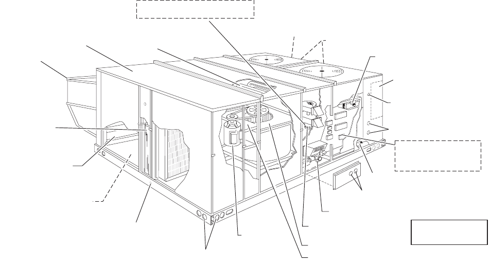
FIGURE 1 - UNIT CUTAWAY
ELECTRICAL DISCONNECT
MOUNTING LOCATION
(Field installed)
KNOCKOUT FOR
SIDE CONTROL WIRING ENTRY
KNOCKOUT FOR
SIDE POWER WIRING ENTRY SIDE
TERMINAL BLOCK
(For Single Point Power Supply
with Electric Heat)
ELECTRIC\ELECTRIC UNITS
BOTTOM POWER & CONTROL
WIRING ENTRY
KNOCKOUTS FOR SIDE
GAS SUPPLY ENTRY
HOLE FOR BOTTOM
GAS SUPPLY ENTRY
POWER VENTOR MOTOR
WITH POST PURGE CYCLE
BELT-DRIVE
BLOWER MOTOR
FULL PERIMETER 14 GUAGE BASE
RAILS WITH LIFTING HOLES
1" NPTI
CONDENSATE DRAIN
SIDE AND BOTTOM
SUPPLY & RETURN AIR
DUCT OPENINGS(SIDE X SIDE)
OUTDOOR AIR OPENING
FOR SLIDE-IN/PLUG-IN
INTERNAL ECONOMIZER(OPTION)
2" DISPOSABLE
FILTERS
ECONOMIZER HOOD
LONG LASTING
POWDER PAINT FINISH
20 GAUGE ALUMINIZED STEEL
TUBULAR HEAT EXCHANGERS
COPPER TUBE/ALUMINUM FIN
CONDENSER COILS
LOW VOLTAGE RELAY BOARD
AND TERMINAL STRIP
GAS/ELECTRIC
UNIT SHOWN
ELECTRIC HEATER LOCATION
(OPTIONAL ELECTRIC/ELECTRIC UNITS)
HIGH EFFICIENCY COMPRESSORS
WITH CRANKCASE HEATERS
LOCATION OF VFD (Optional)
LOCATION OF VFD Bypass (Optional)


