


262260-YTG-E-1008
Johnson Controls Unitary Products 9
SSE = Steady State Efficiency (80%) - Output divided by Input
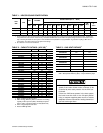
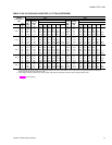
TABLE 1: INDOOR SOUND POWER RATING
1
1. These values have been accessed using a model of sound propagation from a point source into the hemispheric\free field. The dBA val-
ues provided are to be used for reference only. Calculation of dBA values cover matters of system design and the fan manufacture has no
way of knowing the details of each system. This constitutes and expectation to any specification or guarantee requiring a dBA value or
sound data in any other form than sound power level ratings.
UNIT
SIZE
CFM
ESP BLOWER
SOUND POWER (db 10
-12
Watts)
Octave Band Centerline Frequency (Hz)
SWL
dB(A)
dB(A)
@
10Ft.
2
2. At a distance of 10 feet from the blower.
IWG RPM BHP 63 125 250 500 1,000 2,000 4,000 8,000
180 6,000 1.00 1,080 4.60 99 99 89 82 84 77 72 67 89 56
210, 240 8,000 1.00 1,120 6.65 102 102 92 85 87 80 75 70 92 59
300 10,000 1.30 1,160 12.5 108 108 98 91 93 86 81 76 98 65
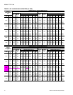
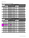
TABLE 2: CAPACITY RATINGS - (ARI 360)
1
1. 80/67°F Indoor and 95°F outdoor.
MODEL MBH
EER
2
2. EER = Energy Efficiency Ratio at full load - the cooling
capacity in Btu’s per hour (Btuh) divided by the power
input in watts, expressed in Btuh per watt (Btuh/watt).
IPLV
3
3. IPLV = Integrated part load value.
COOLING ONLY
DH180C00
178
4
4. Deduct 2 MBH @ 208V.
10.8 11.3
DH210C00
205 10.2 10.8
DH240C00
223 9.7 10.2
DH300C00
271 9.6 9.6
COOLING WITH GAS HEAT
DH180N/S
178
4
10.8 11.3
DH210N/S
205 10.2 10.8
DH240N/S
223 9.7 10.2
DH300N/S
271 9.6 9.6
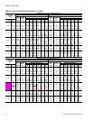
COOLING WITH ELECTRIC HEAT
DH180E18
178
4
10.8 11.3
DH180E36
178
4
10.8 11.3
DH180E54
176
4
10.5 11.0
DH180E72
176
4
10.5 11.0
DH210E18
205 10.2 10.8
DH210E36
205 10.2 10.8
DH210E54
203 10.0 10.6
DH210E72
203 10.0 10.6
DH240E18
223 9.6 10.1
DH240E36
223 9.6 10.1
DH240E54
221 9.5 9.7
DH240E72
219 9.5 9.7
DH300E18
271 9.6 9.6
DH300E36
271 9.6 9.6
DH300E54
269 9.5 9.4
DH300E72
269 9.5 9.4
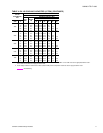
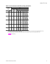
TABLE 3: GAS HEAT RATINGS
1
1. All units are two-stage heating. First stage is 50% of total.
MODEL MBH INPUT MBH OUTPUT
DH180N/S24
300 240
DH180N/S32
400 320
DH210N/S24
300 240
DH210N/S32
400 320
DH240N/S24
300 240
DH240N/S32
400 320
DH300N/S24
300 240
DH300N/S32
400 320
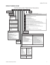
For units with VFD and electric or gas heat, the
speed of the indoor blower motor continues to be
controlled by duct static pressure via the VAV con
-
trol board.
If there are VAV boxes present in the duct system,
the boxes must be driven to the full-open position
using a customer-supplied power source to assure
adequate airflow across electric heating elements or
gas heat exchanger tubes.