


262260-YTG-E-1008
32 Johnson Controls Unitary Products
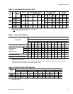
TABLE 25: DH VOLTAGE LIMITATIONS
1
1. Utilization Range “A” in accordance with ARI Standard
110.
POWER SUPPLY
VOLTAGE
MIN. MAX.
208/230-3-60
187 253
460-3-60
414 506
575-3-60
518 506
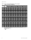
TABLE 26: ELECTRIC HEAT CORRECTION
FACTORS
NOMINAL VOLTAGE VOLTAGE
kW CAP. MULTI-
PLIER
208
208 1.00
240
230 0.92
480
460 0.92
600
575 0.92
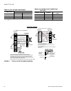
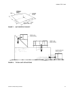
FIGURE 3 - TYPICAL DH FIELD WIRING DIAGRAM
RH
RC
Y1
Y2
W1
W2
G
R
RH
Y1
Y2
W1
W2
G
B
LED1
LED2
COM
A1
A2
T
T
4
4
3
3
Y1
Y2
W1
W2
G
B
X
A1
A2
L1
L3
L2
RC
R
Y1
Y2
W1
W2
G
B
X
A1
A2
Y3
NOT USED
TO REMOTE SENSOR
2THO4702224 IF USED
1
Electronic programmable thermostat 2ET04700224 (includes subbase).
2
Terminal block 1TB- located on relay board in 24-volt section of the unit control box.
3
Second stage heating is not required on units with a single stage electric heater.
4
Terminals A1 and A2 provide a relay output to close the outdoor economizer dampers
when the thermostat switches to the set-back position.
NOTE: Fans switch must be in "ON" position for minimum ventilation during heater operation.
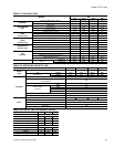
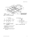
LINE VOLTAGE
TERMINAL
BLOCK 2TB
IN CONTROL BOX
GROUND LUG
Refer to the
ELECTRICAL DATA
tables to size the
power wiring, the
fuses and the
disconnect switch.
24 VOLT
TRANSFORMER
COOLING / HEATING (24 VOLT THERMOSTAT)
THERMOSTAT
1
TERMINALS
CONTROL WIRING
UNIT TERMINAL
BLOCK 1TB
2
1
24 Volt Thermostat 2TH04701024 or 2TH04701524
(with Subbase 2TB04700324).
2
Terminal strip 1TB - located on relay board in 24-volt section
of the unit control box.
3
Second stage heating is not required on units with a single stage
electric heater.
THERMOSTAT
1
TERMINALS
UNIT TERMINAL
BLOCK 1 TB
2
COOLING ONLY (24 VOLT THERMOSTAT)
24 VOLT
TRANSFORMER
POWER WIRING
ADD
JUMPER
ADD
JUMPER
ADD
JUMPER