


035-16328-002Rev. C (0902)
SUPPLY DUCT
LOCATOR BRACKET
_ NAIL_,AFLEATHEAD SCREWS
FLOOR
SUPPLY DUCT
NAILS, FLAT HEAD SCREWS
OR STAPLES
BEND TABS UNDER
OPENING TO
SECURE TO THE
SUPPLY DUCT
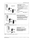
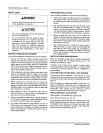
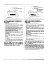
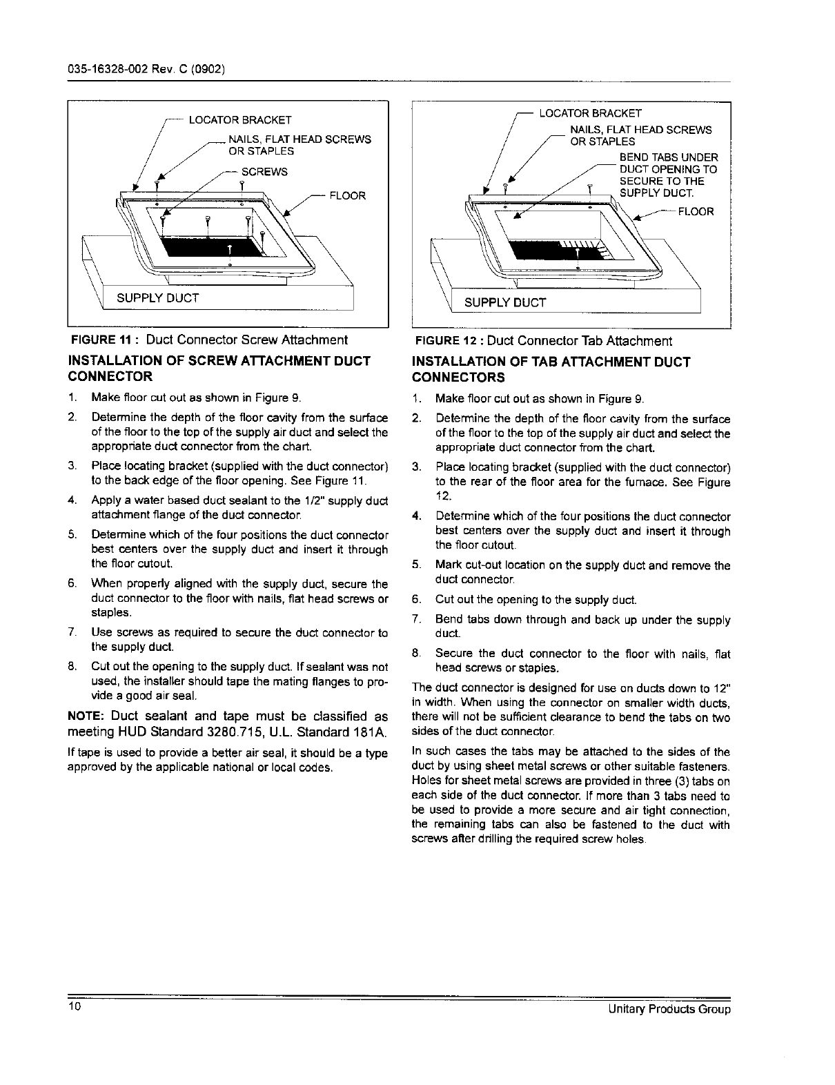
FIGUREtl : Duct Connector Screw Attachment
INSTALLATION OF SCREW A'B'ACHMENT DUCT
CONNECTOR
1,
2.
3.
4.
5.
Make floor cut out as shown in Figure 9.
Determine the depth of the floor cavity from the surface
of the floor to the top of the supply air duct and select the
appropriate duct connector from the chart.
Place locating bracket (supplied with the duct connector)
to the back edge of the flooropening. See Figure 11.
Apply a water based duct sealant to the 1/2"supplyduct
attachment flange of the duct connector.
Determine which of the four positions the duct connector
best centers over the supply duct and insert it through
the floor cutout.
6. When propedy aligned with the supply duct, secure the
duct connector to the floor with nails, flat head screws or
staples.
7. Use screws as required to secure the duct connector to
the supply duct.
8. Cut out the opening to the supplyduct. Ifsealant was not
used, the instaner should tape the mating flanges to pro-
vide s good air seal.
NOTE: Duct sealant and tape must be classified as
meeting HUD Standard 3280.715, U.L. Standard 181A.
If tape is used to provide a better air seal, it should be a type
approved by the applicable national or local codes.
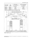
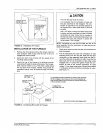
FIGURE t2 : Duct Connector TabAttachment
INSTALLATION OF TAB ATTACHMENT DUCT
CONNECTORS
1. Make floor cut out as shown in Figure 9.
2. Determine the depth of the floor cavity from the surface
of the floor to the top of the supply air duct and select the
appropriate duct connector from the chart.
3. Place locating bracket (supplied with the duct connector)
to the rear of the floor area for the furnace. See Figure
12.
4. Determine whichof the four positions the duct connector
best centers over the supply duct and insert it through
the floor cutout.
5. Mark cut-out location on the supplyduct and remove the
duct connector.
6. Cut out the opening to the supplyduct.
7. Bend tabs down through and back up under the supply
duct.
8. Secure the duct connector to the floor with nails, flat
head screws or staples.
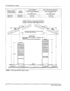
The duct connector is designed for use on ducts down to 12"
in width. When using the connector on smaller width ducts,
there will not be sufficientclearance to bend the tabs on two
sides of the duct connector.
In such cases the tabs may be attached to the sides of the
duct by using sheet metal screws or other suitable fasteners.
Holes for sheet metal screws are provided inthree (3) tabs on
each side of the duct connector. If more than 3 tabs need to
be used to provide a more secure and air tight connection,
the remaining tabs can also be fastened to the duct with
screws after drilling the required screw holes.
10 Unitary Products Group