


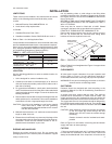
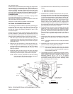
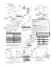


Install the bracket on the left hand side of the unit as shown in
Figure 5. Several existing screws at the top of the unit and one
screw approximatelymidway down fromthe top willbe usedfor
mounting the bracket. Screws should be loosened only - NOT
REMOVED. Matching holes in the bracket have elongated
keyways allowing easy installation. Re-tighten screws after
bracket is in place to ensure panels will remain leak tight.
ELECTRIC HEATERS
Electric heaters are available as field-installed accessories.
Refer to Form 530.18-N7.1V for installation instruction. These
UL approved heaters are located within the central
compartment of the unit (see Figure 5 for access panel) with
the heating elements extending into the supply air chamber.
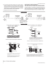
The heaters are wired for a single point power supply. Power
supply needonly be brought intothe single pointterminal block
035-12046-003-A-0204
8 Unitary Products Group
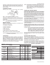
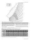
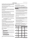
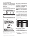
FIG. 6 - ENTHALPY SET POINT ADJUSTMENT
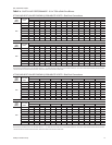
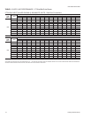
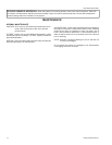
TABLE 3 - SUPPLY AIR PERFORMANCE - 3 THRU 5 TON
w/Direct-Drive Blower
UNIT
SIZE
(MBH)
MOTOR
SPEED
Available External Static Pressure - IWG*
0.20 0.30 0.40 0.50 0.60 0.70 0.80 0.90 1.00
CFM Watts CFM Watts CFM Watts CFM Watts CFM Watts CFM Watts CFM Watts CFM Watts CFM Watts
036
HI
MED
LOW
-
1684
1487
-
800
710
-
1631
1464
-
780
690
1699
1582
1421
825
750
670
1650
1524
1367
785
720
650
1570
1410
1315
755
690
620
1430
1324
1246
725
650
605
1360
1260
1185
700
630
590
1280
1185
1110
680
610
570
1180
1100
1020
655
590
545
048
HI
MED
LOW
1996
1804
1681
960
838
760
1933
1765
1640
936
810
738
1868
1714
1604
910
785
715
1795
1650
1541
880
765
695
1722
1589
1490
845
735
670
1635
1508
1416
820
705
645
1544
1407
1337
790
675
620
1419
1306
1230
765
645
595
1300
1195
1120
740
625
575
060
HI
MED
LOW
2400
2290
2150
1155
1105
1020
2338
2214
2100
1125
1065
990
2274
2145
2029
1095
1030
950
2167
2071
1965
1045
990
910
2096
1990
1905
1010
950
880
1990
1911
1816
980
920
838
1887
1828
1724
945
885
800
1771
1724
1644
905
835
770
1629
1604
1531
855
798
710
NOTE: FOR 208 VOLTS, MULTIPLY VALUES BY 0.95.
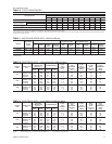
*INCLUDES ALLOWANCES FOR AWET EVAPORATOR COIL, 1" FILTERS AND GAS-FIRED HEAT EXCHANGERS. REFER TO THE STATIC RESISTANCES TABLE FOR RESISTANCE
VALUES ON APPLICATIONS OTHER THAN GAS / ELECTRIC UNITS WITH SIDE DUCT AIRFLOWS.
GAS HEAT VALUES SHOWN @ 230/460/575 VOLTS
- Side Duct Connections