


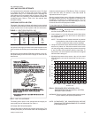


kept clean or replaced with same size and type. Dirty filters will
reduce the capacity of the unit and will result in frosted coils or
safety shutdown. Minimum filter area and required sizes are
shown in Table 2.
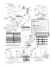
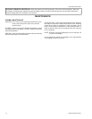
CONDENSATE DRAIN
Plumbing must conform to local codes. Use a sealing
compound on male pipe threads. Install a condensate drain
line fromthe 3/4" PVCfemale connection onthe unit tospill into
an open drain.
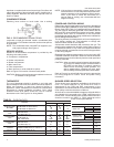
NOTE: The condensate drain line MUST be trapped to pro
-
vide proper drainage. See Figure 2.
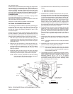
SERVICE ACCESS
Access to all serviceable components is provided by the
following removable panels:
•
Compressor compartment
•
Heater compartment
•
Blower compartment
•
Main control box
•
Filter compartment
•
Motor Access (on units w/belt-drive option)
Refer to Figure 5 for location of these access panels.
CAUTION: Make sure that all screws are replaced on the unit
to maintain an air-tight seal.
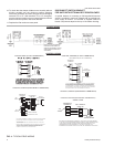
THERMOSTAT
The room thermostat should be located on an inside wall
approximately 56" above the floorwhere it will not be subject to
drafts, sun exposure, or heat from electrical fixtures or
appliances. Follow manufacturer's instructions enclosed with
thermostat for general installation procedure. Color coded
insulated wires (#18 AWG) should be used to connect
thermostat to unit. See Figure 4 for wiring details.
NOTE: If the unit has an economizer, remove jumper J1 from
terminals 8 and10 on the relay boardto prevent simul
-
taneous operation of the compressor and the econo
-
mizer. If you want to control the economizer on a
second stage of cooling, use a thermostat with two
stages of cooling.
POWER AND CONTROL WIRING
Field wiring to the unit must conform to provisions of the National
Electrical Code(NEC) ANSI/NFPA70(in USA),current Canadian
Electric Code (CEC) C22.1 (in Canada) and/or local ordinances.
The unit must be electrically grounded in accordance with the
NEC and CEC (as specified above) and/or local codes. Voltage
tolerances which must be maintained at the compressor
terminals during starting and running conditions are indicated on
the unit Rating Plate and Table 1.
The wiring harness furnished with this unit is an integral part of
a UL design certified unit. Field alteration to comply with
electrical codes should not be required.
A disconnect switch should be field provided for the unit. The
switch must be separate from all other circuits. Refer to Figure 5
for installation location. If any of the wire supplied with the unit
must be replaced, replacementwire must be of the typeshown
on the wiring diagram.
Electrical lines must be sized properly to carry the load. USE
COPPER CONDUCTORS ONLY. Each unitmust be wiredwith
a separate branch circuit fed directly from the meter panel and
properly protected.
CAUTION: When connecting electrical power and control wir-
ing to the unit, waterproof type connectors MUST
BE USED so that water or moisture cannot be
drawn into the unit during normal operation. The
above waterproofing conditions will also apply
when installinga field-supplieddisconnectswitch.
Refer to Figure 4 for typical field wiring and to the appropriate
unit wiring diagram for control circuit and power wiring
information.
BLOWER SPEED SELECTION
Three blower motor speeds are available on the direct-drive
units. The speed selection for the direct-drive units is
determined by the CFM and ESP requirements of the
applications. All units with belt-drive option have an adjustable
motor pulley to achieve the above conditions.
All direct-drive units with 208/230 voltage are shipped with the
wire labeled #116 connected to the “HIGH” speed tap on the
blower motor.If alower blowermotor speedis desired,this wire
should be moved to the “MED” or “LOW” speed tap on the
motor for the speed desired.
035-12046-003-A-0204
4 Unitary Products Group
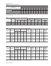
FIG. 2 - RECOMMENDED DRAIN PIPING
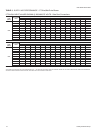
WEIGHTS (LBS)
Basic Unit
3 Ton 545
4 Ton 585
5 Ton 610
ACCESSORIES / OPTIONS
Electric Heat
(Nominal KW)
5 - 7 KW 18
10 - 15 KW 23
20 - 30 KW 28
Economizer 50
Motorized Outdoor
Air Damper
26
Relief/Fixed
Air Damper
10
Roof Mounting Curb 92
Belt-Drive Blower 5
MODELS
DEE
036 048 060
EVAPORATOR
BLOWER
CENTRIFUGAL BLOWER (Dia. x Wd. in.)
FAN MOTOR HP (Direct-Drive)
FAN MOTOR HP (Belt-Drive)
12 x 10
1.5
12 x 10
1.5
12 x 10
1
1.5
EVAPORATOR
COIL
ROWS DEEP
FINS PER INCH
FACE AREA (Sq. Ft.)
3
13
3.6
3
13
4.3
3
13
5.1
CONDENSER
FAN
PROPELLER DIA. (in.)
FAN MOTOR HP
NOM. CFM TOTAL
22
4,500
22
4,200
22
4,500
CONDENSER
COIL
ROWS DEEP
FINS PER INCH
FACE AREA (Sq. Ft.)
2
18
17.1
2
18
17.1
2
18
17.1
AIR
FILTERS
(SEE NOTE)
QUANTITY PER UNIT (15" x 20" x 1")
QUANTITY PER UNIT (14" X 25" X 1")
TOTAL FACE AREA (sq. ft.)
2
1
6.6
2
1
6.6
2
1
6.6
CHARGE REFRIGERANT 22 (lbs./oz.) 9/12 9/8 9/8
COMPRESSOR QUANTITY PER UNIT (HERMETIC TYPE) 1/RECPT 1/RECPT 1/SCROLL
NOTE: Filter racks are adapted for 1" or 2" thick filters.
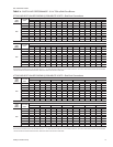
TABLE 2 - PHYSICAL DATA