


LIMITATIONS
These units must be installed in accordance with the current
edition of the following national and local safety codes:
In USA:
1. National Electrical Code ANSI/NFPA No. 70.
2. Local electric utility requirements.
In Canada:
1. Canadian Electrical Code C22.1.
2. Canadian Installation Codes CAN/CGA-B149.1 and .2.
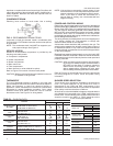
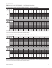
Refer to Table 1 for Unit Application Data.
If components are to be added to a unit to meet local codes, they
are to be installedat thedealer'sand /or thecustomer's expense.
Size of unit for proposed installation should be based on heat
loss / heat gain calculation made according to the methods of
Air Conditioning Contractors of America (ACCA).
LOCATION
Use the following guidelines to select a suitable location for
these units.
1. Unit is designed for outdoor installation only.
2. Condenser must have an unlimited supply of air. Where a
choice oflocation ispossible, position uniton eithernorth or
east side of building.
3. For ground level installation, a level pad or slab should be
used. Thethickness andsize of thepad orslab usedshould
meet local codes and unit weight. Do not tie the slab to the
building foundation.
4. Roof structures must be able to support the weight of the unit
and its options and / or accessories. Unit must be installed on
a solid level roof curb or appropriate angle iron frame.
CAUTION: If a unit is to be installed on a roof curb or special
frame other than a YORK roof curb, gasketing
must beapplied to allsurfaces thatcome in contact
with the unit underside.
5. Maintain level tolerance to 1/2" maximum across the entire
length or width of the unit.
6. Elevate the unit sufficiently to prevent any blockage of the
air entrances bysnow in areaswhere there will besnow ac
-
cumulation. Check the local weather bureau for the ex
-
pected snow accumulation in your area.
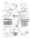
RIGGING AND HANDLING
Exercise care when moving the unit. Do not remove any
packaging until the unit is near the place of installation. Rig the
unit by attaching chain or cable slings to the lifting holes
provided in the base rails. Spreaders, whose length exceeds
the largest dimension across the unit, MUST be used across
the top of the unit.
BEFORE LIFTING A UNIT, MAKE SURE THAT ITS WEIGHT
IS DISTRIBUTED EQUALLY ON THE CABLES SO THAT IT
WILL LIFT EVENLY.
Units may also be moved or lifted with a forklift. Slotted
openings in the base rails are provided for this purpose.
LENGTH OF FORKS MUST BE A MINIMUM OF 42".
Remove the nesting brackets from the four corners on top of
the unit. All screws that are removed when taking these
brackets off must be replaced on the unit.
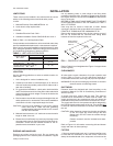
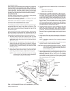
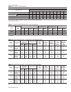
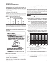
Refer toTable 2for unitweights andto Figure1 forapproximate
center of gravity.
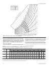
CLEARANCES
All units require certain clearances for proper operation and
service. Refer to Figure 5 for the clearances required for
combustible construction,servicing, andproperunit operation.
WARNING:Do not permit overhanging structures or shrubs to
obstruct outdoor air discharge outlet.
DUCTWORK
Ductwork should be designed and sized according to the
methods in Manual Q of the Air Conditioning Contractors of
America (ACCA).
A closed return duct system shall be used. This shall not
preclude use of economizers or outdoor fresh air intake. The
supply and return air duct connections at the unit should be
made withflexible jointstominimize thetransmission ofnoise.
The supply and return air duct systems should be designed for
the CFM and static requirements of the job. They should NOT
be sized to match the dimensions of the duct connections on
the unit.
CAUTION: When fastening ductwork to the side duct flanges
on the unit, insert the screws through the duct
flanges only. DO NOT insert the screws through
the casing.
Outdoor ductwork must be insulated and water
-
proofed.
Refer to Figure 5 for information concerning side and bottom
supply and return air duct openings.
FILTERS
1" filters are supplied witheach unit. 2" replacement filters may
be used with no modification to the filter racks. Filters must
always be installed ahead of the evaporator coil and must be
035-12046-003-A-0204
Unitary Products Group 3
INSTALLATION
Voltage Variation
Min. / Max
.1
208/230V 187 / 253
460V 414 / 504
575V 518 / 630
Wet Bulb Temperature (°F) of Air on
Evaporator Coil, Min. / Max.
57 / 72
Dry Bulb Temperature (°F) of Air on
Condenser Coil, Min.
2
/ Max.
45 / 120
1
Utilization range “A” in accordance with ARI Standard 110.
2
Alow ambient accessory is available for operation down to 0°F
TABLE 1 - UNIT APPLICATION DATA
APPROXIMATE
CENTER OF
GRAVITY
FRONT
67-3/4
30
30-1/2
15-1/8
FIG. 1 - CENTER OF GRAVITY
“
B
“
A
Dim. 3-5 Ton
A 19-3/4"
B 40-3/4"