


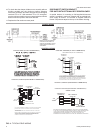


All direct-drive units with 460 and 575 voltage are shipped with
the wire labeled #116 connected to the “HIGH” speed tap on
the blowermotor. Ifthe mediumspeed isrequired, connectwire
#116 to the “MED” speed tap and the blue motor lead to the
“HIGH” speed tap. If the low speed is required, connect wire
#116 to the“LOW” speed tap,the blue motorlead to the“HIGH”
speed tapand theorangemotor leadto the“MED” speedtap.
COMPRESSORS
On some units the compressor is mounted on springs which
have been tightened down for shipment only.
After this unit is installed, back out the compressor bolts until
the sleeve clears the top grommet.
CAUTION: Do Not loosen compressor mounting bolts.
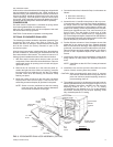
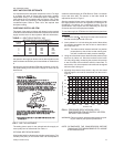
OPTIONAL ECONOMIZER RAIN HOOD
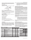
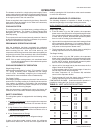
The following procedure should be used when assembling an
economizer rain hood onto a unit. Refer to Figure 3. The
outdoor and return air dampers, damper actuator, the linkage
and all the controls are factory mounted as part of the
economizer option.
All of the hood components, including the filters, the gasketing
and the hardware for assembling are located above the top
filter racks within the filter section. The outdoor air sensor is in
the bagof partslocatedat thebottom ofthe returnair section.
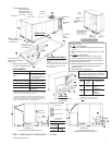
1. With filter section access panel removed, take out hood
components, filters and sensor described above. Remove
and discard outdoor air opening cover on back unit (Upper
right hand corner).
2. Remove the 1/2" knockout (A) in the units rear panel (lo-
cated to the right side of theoutdoor air opening). Insert the
two loose wires from inside the unit, into the 1/2" bushing
provided. Insert wires and bushing into knockout. Snap
bushing into place.
3. Mount the outdoor air sensor to the rear panel, just below
the knockout described in Step 2. Secure with two
self-drilling screws at dimples (B) provided in the panel.
NOTE: Sensor must be positioned so that the sensing
ports are at the top (louvers pointing downward)
and terminal connections to the right.
4. Connectthe two wires, indicated inStep 2, to the sensor as
follows:
•
Wire #73 to terminal (+)
•
Wire #74 to terminal (S)
5. Assemble the LH and RH side plates to the top cover
(2 screws each side) to form the hood. Apply gasketing to
the flange surface on each side plate. Extend gasketing
1/4" beyond top and bottom of each flange to insure ade
-
quate corner sealing.Secure this assemblyto the unit back
panel (upper right handcorner). First, remove screw (C)on
unit top cover. Then slip flange of hood cover in under
flange of unit top cover, replace screw (C), engaging hole
(E) in hood flange and tighten. Attach the two side platesto
the unit panelby using twoself-drilling screws foreach side
plate at dimples (D) provided in the panel.
6. Position fillpiece at bottom of hood, between the two side
plates but do not secure at this time. (Slotted openings
MUSTbe downward fordrainage). Afterfillpiece is properly
positioned, note where contact is made with the unit panel.
Remove fillpiece and apply gasket material to this area to
provide a seal. Reposition fillpiece and secure with 2
screws.
7. Install the two filters into the hood assembly, sliding down
along retainers on side plates, into fillpiece at bottom of
hood.
NOTE: Install filters so that “Air Flow” arrows point toward
the unit.
8. Install filter cover over the end of the hood with one screw
(center of hood), securing filters into position.
CAUTION: When proceeding with steps 9 and 10, extreme
care must be exercised while turning both the set
point and minimum position adjusting screws to
prevent twisting them off.
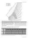
9. The enthalpy set point for the dampers may now be set by
selecting the desiredset-point from graphin Figure 6.For a
single enthalpy economizer, carefully turn the set-point
adjusting screw to the “A”, “B”, “C” or “D” setting
corresponding to the lettered curve. For a dual enthalpy
economizer, carefully turn the set-point adjusting screw
fully clockwise past the “D” setting.
035-12046-003-A-0204
Unitary Products Group 5
FIG. 3 - ECONOMIZER RAIN HOOD ASSEMBLY (OPTION)
B
GASKET
C
HOOD
COVER
OUTDOOR AIR
SENSOR
A
FILTER SECTION
ACCESS PANEL
D
GASKETED
FLANGE
R. H.
SIDE
PLATE
D
E
D
D
GASKETED
FLANGE
FILTER
COVER
L. H. SIDE
PLATE
FILTERS
FILLPIECE
OUTDOOR AIR
OPENING COVER
SIDE DUCT
APPLICATION SHOWN