


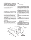


HEAT ANTICIPATOR SETPOINTS
It is important that the anticipator setpoint be correct. Too high
of a setting will result in longer heat cycles and a greater
temperature swing in the conditioned space. Reducing the
value below the correct setpoint will give shorter “ON” cycles
and may result in the lowering of the temperature within the
conditioned space. Refer to Table 10 for the required heat
anticipator setting.
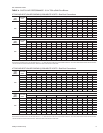
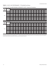
CHECKING SUPPLY AIR CFM
The speed of the supply air blower will depend on the required
CFM, theunit accessoriesand thestatic resistancesof boththe
supply and the return air duct systems. With this information,
the speed for the supply air blower can be determined from the
static resistance andblower performance data onTables 3thru
6.
Knowing the required blower RPM and the blower motor HP,
the speed setting for the direct-drive supply air motor can be
determined.
The setting (turns open) for the optional belt-drive supply air
motor pulley can be determined from Table 11.
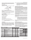
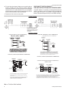
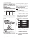
OPTIONAL BELT-DRIVE BLOWER
All units with belt-drive blowers havesingle-speed motors. The
variable pitch pulley on the blower motor can be adjusted to
obtain the desired supply air CFM. Refer to Table 7 for blower
motor and drive data. The tension on the belts should be
adjusted as shown in Figure 7.
Start thesupply air blowermotor. Adjust theresistances inboth
the supply and the return air duct systems to balance the air
distribution throughout the conditioned space. The job
specifications may require that this balancing be done by
someone other than the equipment installer.
Tocheck thesupply air CFMafter theinitial balancing hasbeen
completed:
1. Remove the (two) " dot plugs from the holes located on
the filter access panel side of the unit.
2. Insert at least 8" of 1/4 inch tubing into each of these holes
for sufficient penetration into the air flow on both sides of
the evaporator coil.
NOTE: The tubes must be inserted and held in a position
perpendicular to the air flow so that velocity pres
-
sure will not affect the static pressure readings.
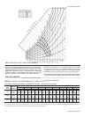
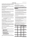
3. Usingan inclined manometer, determinethe pressure drop
across a dry indoor coil. Since the moisture on an indoor
coil may vary greatly, measuring the pressure drop across
a wet coil under field conditions would be inaccurate. To
assure a dry coil, the compressors should be de-energized
while the test is being run.
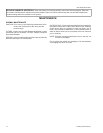
4. Knowing the pressure drop across a dry coil, the actual
CFM through the unit can be determined from the curve in
Figure 8.
WARNING:Failure to properlyadjust the total systemair quan
-
tity can result in poor system performance.
NOTE: DE-ENERGIZE THE COMPRESSORS BEFORE
TAKING ANY TEST MEASUREMENTS TO ASSURE
A DRY INDOOR COIL.
035-12046-003-A-0204
Unitary Products Group 13
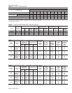
TURNS
OPEN*
BLOWER DRIVE RANGE (RPM)
3 TON 4 TON 5 TON
5
4
3
2
1
0
780
842
904
966
1028
1090
790
856
922
988
1054
1120
850
924
998
1072
1246
1220
*Pulley can be adjusted in half-turn increments.
TABLE 11 - BELT-DRIVE SUPPLY AIR
MOTOR PULLEY ADJUSTMENT
FIG. 7 - BELT ADJUSTMENT
0
0.1
0.2
0.3
0.4
0.5
0.6
0.7
750 1250 1750 2250 2750 3250 3750
036
048
NOMINAL CFM
PRESSURE DROP (IWG)
060
FIG. 8 - PRESSURE DROP ACROSS A DRY
EVAPORATOR COIL VS SUPPLY AIR CFM,
WITHOUT AIR FILTERS