


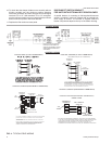

The heaters are wired for a single point power supply. Power
supply need onlybe brought into the singlepoint terminal block
and thermostat wiring to the low voltage terminal strip located
in the upper portion of the unit control box.
Fuses are supplied, where required, by the factory. Some KW
sizes require fuses and others do not. Refer to the accessory
instruction for electrical data.
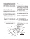
COOLING SYSTEM
The cooling section is a complete factory package utilizing an
air-cooled condenser. The system is factory-charged with
Refrigerant-22. The compressor is hermetically sealed and
internally sprung.
The compressors have inherent (internal) protection. If there is
an abnormal temperature rise in the compressor, the protector
will open to shut down the compressor.
PRELIMINARY OPERATION COOLING
After the installation has been completed, the crankcase
heater ofthe compressormust beenergized for atleast 4hours
before starting the unit. After this initial warm-up, the
compressor should be given three false starts (energized just
long enough to make a few revolutions) with a 5 minute delay
between each start before being put into full time service.
NOTE: Prior to each cooling season, the crankcase heater
must be energized at least 10 hours before thesystem
is put into operation.
COOLING SEQUENCE OF OPERATION
Single-Stage Cooling:
When the thermostatcalls for “cooling”, “R”is closed to “G” and
“Y1" (wiring schematic) which completes the low voltage
control circuit, immediately energizing the compressors,
condenser fan motor and blower motor simultaneously.
Two-Stage Cooling:
A two-stage cooling thermostat may be used if the unit has an
economizer. First-stage cooling is provided by the economizer
if the outdoor air enthalpy is acceptable, and second-stage
cooling is providedby the compressor. Jumper wire J1 mustbe
removed. Refer to unit wiring diagram.
After the thermostat is satisfied and opens, the blower will
continue torun forashort time.All othercomponents willstop.
SAFETY CONTROLS
The refrigerant system is equipped with the following safety
controls:
1. ASuction Line Freezestat
to protectagainst low evaporator
temperatures due to a low air flow or a low return air tem
-
perature.
2. AHigh PressureCutout Switch
to protectagainst excessive
discharge pressures due to a blocked condenser coil or a
condenser motor failure.
3. A Low Pressure/Loss of Charge
Switch to protect against loss of refrigerant charge.
If either of the above safety controls opens, the refrigerant
system will be locked out. The lock out of the system can be
reset by opening the 24V circuit either at the room thermostat
or at the unit disconnect.
HEATING SEQUENCE OF OPERATION
The following sequence of operation is based on using a
standard single-stage or two-stage heating thermostat.
WITH POWER TO UNIT AND THERMOSTAT IN THE
HEATING MODE
Single-Stage Heating:
a. If the fan switch is in the “ON” position, the evaporator
blower motor relay (BR) will be energized through terminal
G to provide continuous blower operation. If the fan switch
is in the “AUTO” position, the blower will operate only when
there is a call for heating by the thermostat.
b. Upona callfor heat bythe thermostat,the firststage of heat
will be energized. Sequencer 1S (or contactor 2M) is al
-
ways the first and last to complete its timing cycle and con
-
trols power to the evaporator blower motor.
c. The thermostat will cycle the electric heat to satisfy the
heating requirements of the conditioned space.
Two-Stage Heating:
a. If the fan switch is in the “ON” position, the evaporator
blower motor relay (BR) will be energized through terminal
G to provide continuous blower operation. If the fan switch
is in the “AUTO” position, the blower will operate only when
there is a call for heating by the thermostat.
b. Upon a call for first-stage heat by the thermostat, the first
stage of heat will be energized.
If the thermostat calls for the second stage of heat, the
second stage of heat will be energized.
As before, sequencer 1S (or contactor 2M) maintains
control of the evaporator blower.
c. The thermostat will cycle the electric heat to satisfy the
heating requirements of the conditioned space.
CONTINUOUS BLOWER - Continuous blower operation is
possible by closing the R to G circuit on the thermostat.
035-12046-003-A-0204
12 Unitary Products Group
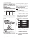
OPERATION
NOMINAL
HEATER
SIZE
KW
VOLTAGE
SETTING, AMPS
TH1 TH2
5
7
10
15
20
30
240-1-60
0.16
0.35
0.35
0.35
0.35
0.35
-
-
-
0.19
0.38
0.38
5
7
10
15
20
30
240-3-60
0.35
0.35
0.35
0.35
0.35
0.35
-
-
-
0.19
0.38
0.38
7
10
15
20
30
480-3-60
0.35
0.35
0.35
0.37
0.37
-
-
-
0.29
0.29
10
15
20
30
600-3-60
0.35
0.35
0.37
0.37
-
-
0.29
0.29
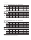
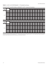
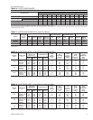
TABLE 10 - HEAT ANTICIPATOR SETTING