


66307-YIM-B-0606
20 Unitary Products Group
MOTORIZED OUTDOOR DAMPER
The Motorized Outdoor Damper can be a factory installed
option or a field installed accessory. If factory installed, refer
to the instructions included with the outdoor air hood to com-
plete the assembly. Field installed Motorized Outdoor
Damper accessories include complete instructions for instal-
lation.
ECONOMIZER
The Economizer can be a factory installed option or a field
installed accessory. If factory installed, refer to the instruc-
tions included with the outdoor air hood to complete the
assembly. Field installed Economizer accessories include
complete instructions for installation.
There are two Economizer options:
1. Down Flow application with barometric relief hood stan-
dard.
2. Horizontal Flow application that requires the purchase of
a barometric relief hood.
POWER EXHAUST
The Power Exhaust can be a factory installed option or a field
installed accessory. If factory installed, refer to the instruc-
tions included with the outdoor air hood to complete the
assembly. Field installed Power Exhaust accessories include
complete instructions for installation.
The Power Exhaust factory installed option is for Down Flow
application only.
There are two field installed Power Exhaust accessories:
1. Down Flow application.
2. Horizontal Flow application that requires the purchase of
a barometric relief hood.
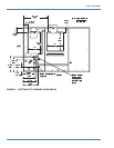
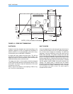
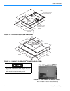
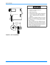
RAIN HOOD
All of the hood components, including the filters, the gasket-
ing and the hardware for assembling, are packaged and
located between the condenser coil section and the main unit
cabinet, if the unit has factory installed options. If field
installed accessories are being installed all parts necessary
for the installation comes in the accessory.
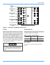
ECONOMIZER AND POWER EXHAUST SET POINT
ADJUSTMENTS AND INFORMATION
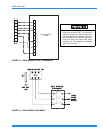
Remove the top rear access panel from the unit. Locate the
economizer control module, where the following adjustments
will be made.
MINIMUM POSITION ADJUSTMENT
• Check that the damper blades move smoothly without
binding; carefully turn the Minimum Position Adjust
screw (found on the damper control module) fully clock-
wise and then set the thermostat indoor fan switch to the
ON position and then OFF or energize and de-energize
terminals “R” to “G”.
• With the thermostat set to the indoor fan ON position or
terminals “R” to “G” energized, turn the Minimum Posi-
tion Adjusting screw (located on the damper control
module) counterclockwise until the desired minimum
damper position has been attained.
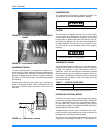
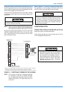
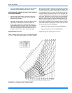
ENTHALPY SET POINT ADJUSTMENT
The enthalpy set point may now be set by selecting the
desired set point shown in the Enthalpy Set Point Adjustment
Figure 20. Adjust as follows:
• For a single enthalpy operation carefully turn the set
point adjusting screw (found on the damper control mod-
ule) to the "A", "B", "C" or "D" setting corresponding to
the lettered curve of the Enthalpy Set Point Adjustment
Figure 20.
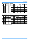
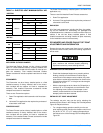
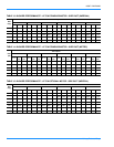
TABLE 11: ELECTRIC HEAT MINIMUM SUPPLY AIR
IMPERIAL
HEATER UNIT MODEL SIZE, NOMINAL TONS
kW
VOLTAGE
7.5 10
MINIMUM SUPPLY AIR CFM
9
380/415
2250 N/A
18
2250 3000
24
2250 3000
36
2250 3000
54
N/A 3000
METRIC
HEATER UNIT MODEL SIZE, NOMINAL TONS
kW
VOLTAGE
7.5 10
MINIMUM SUPPLY AIR M
3
S
9
380/415
1.06 N/A
18
1.06 1.42
24
1.06 1.42
36
1.06 1.42
54
N/A 1.42
Extreme care must be exercised in turning all set
point, maximum and minimum damper positioning
adjustment screws to prevent twisting them off.