


292443-XTG-D-0508
24 Johnson Controls Unitary Products
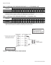
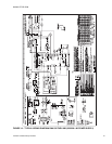
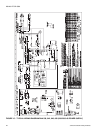
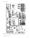
TYPICAL WIRING DIAGRAM NOTES
(SEE FIGURE 14 THRU 16)
1. All field wiring to be accomplished following city, local
and/or national codes in effect at time of installation of
this unit.
2. Caution: Label all wires prior to disconnection when ser-
vicing controls. Wiring errors can cause improper and
dangerous operation. If any of the wire as supplied with
this unit must be removed it must be replaced with type
105°C, 600V wire or equivalent clearly renumbered for
identification. Verify proper operation after servicing.
3. Motors inherently protected.
4. Factory wired for 230V. For 208V operation, move wire
107/PR to 208V. Tap on transformer T1.
5. See unit nameplate for maximum fuse size and/or circuit
breaker size and minimum circuit ampacity.
6. If both LR and ASCT are present, wire 801/BL and 805/
BL are connected to ASCT-3. If only LR is present wire
801/BL and 805/BL are connected to M1 coil. If only
ASCT is present wire 202/Y is connected to ASCT-3. If
neither LR or ASCT are present, wire 202/Y is connected
to M1 coil as shown.
7. Shunt contact also used with crankcase heater.
(optional)
8. Select indoor blower speed to remain within the temper-
ature rise range on the nameplate in heating.
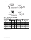
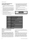
FIGURE 17 - TYPICAL WIRING DIAGRAM LEGEND
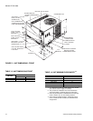
MECHANICAL SPECIFICATIONS
GENERAL
Units shall be manufactured by York International Unitary
Products Group in an ISO 9001 certified facility. YORK’s
Affinity™ package units are designed to handle applications
ranging from residential to light commercial and any in
between. The Affinity™ is a unit that gives you the flexibility
and choices you need in today’s market. These packaged
cooling/heating air conditioners are designed for outdoor
installation. Only utility and duct connections are required at
the point of installation. The gas fired heaters have alumi-
nized steel tubular heat exchangers and spark to pilot igni-
tion. They are available in natural gas with field conversion to
propane.
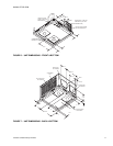
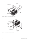
DESCRIPTION
Units shall be factory-assembled, single packaged, Electric
Cooling/Gas Heating units, designed for outdoor mounted
installation. For EER ratings, refer to technical literature.
They shall have built in, equal size, field convertible duct
connections for down discharge supply/return or horizontal
discharge supply/return. The units shall be factory wired,
piped, charged with R-22 refrigerant and factory tested prior
Open all disconnects before servicing this unit.
LEGEND
ALS AUXILARY LIMIT SWITCH
ASCT ANTI-SHORT CYCLE TIMER (OPTIONAL)
BR BLOWER RELAY
CB CIRCUIT BREAKER
CCH CRANK CASE HEATER (OPTIONAL)
COMPR COMPRESSOR
DM DRAFT MOTOR
FCB FAN CONTROL BOARD
GND GROUND
FS FREEZE STAT SWITCH (OPTIONAL)
HP HIGH PRESSURE SWITCH OPENS @ 380 PSIG
IDFAN INDOOR FAN MOTOR
LP LOW PRESSURE SWITCH OPENS @ 7 PSIG
LS LIMIT SWITCH
LR LOCK OUT RELAY (OPTIONAL)
M1 CONTACTOR, COMPR. AND OD FAN
ODFAN OUTDOOR FAN MOTOR
PS PRESSURE SWITCH
RC1 / RC2 COMPRESSOR START & OUTDOOR FAN RUN CAPACITOR
RS ROLLOUT SWITCH
TB4 TERMINAL BLOCK
T1 TRANSFORMER, 24V, 230V