


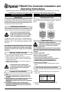
Remove the Cover and Mounting Frame
Eye protection must be worn during all
drilling & chiselling operations.
Check there are no buried Pipes or Cables
in the wall or obstructions on the outside
e.g. Electricity, Gas, Water.
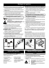
Mounting the Wall Box
If surface mounting
1 Insert suitable glands into the knockouts.
2 Feed both cables through the glands.
3 Fix the Wall Box and Plastic Surround to the wall, using
the mounting holes provided.
4 Reconnect the earth lead to the Wall Box.
If recess mounting
1 Make a hole in the wall big enough to take the Wall Box.
Discard the Plastic Surround.
2 Insert suitable glands into the knockouts.
3 Feed both cables through these glands.
4 Fix the Wall Box to the wall. Ensure that the
flange of the mounting frame fits flush to the finished
surface of the wall (Refer diagram F6).
5 Reconnect the earth lead to the Wall Box.
Wire the Controller electrical connections
1 Mount the Isolation Switch in accordance with the
manufacturers instructions.
2 Wire the Controller to the Isolation Switch and to the Fan
as shown in the appropriate diagram (Refer to Table 1).
3 Refit Mounting Frame to Metal Wall Box.
4 Refit the Fascia to the Mounting Frame.
5 Refit the Screw Covers.
1 Ensure power supply is isolated and fuses are
removed.
2 Route the Cable from the Isolating Switch to the point of
connection to the power supply.
3 Make all connections within the Isolating Switch in
accordance with the manufacturers instructions.
4 Following all local regulations make connection at point of
power supply.
5 Make a final check to ensure all earth points are connected
and all covers have been correctly replaced on the fan,
controller and isolating switch.
6 Replace all fuses, and switch on the power supply.
For fixed wiring circuits the protective fuse for the
appliance must not exceed 5 amps.
For Australia only:
These models are permanently connected to the supply &
operation is controlled by a remote switch. They should be
directly wired to the supply through an approved 10 amp wall
mounted surface switch with at least 3mm clearance between
contacts.
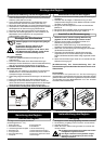
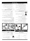
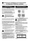
Mounting the Controller
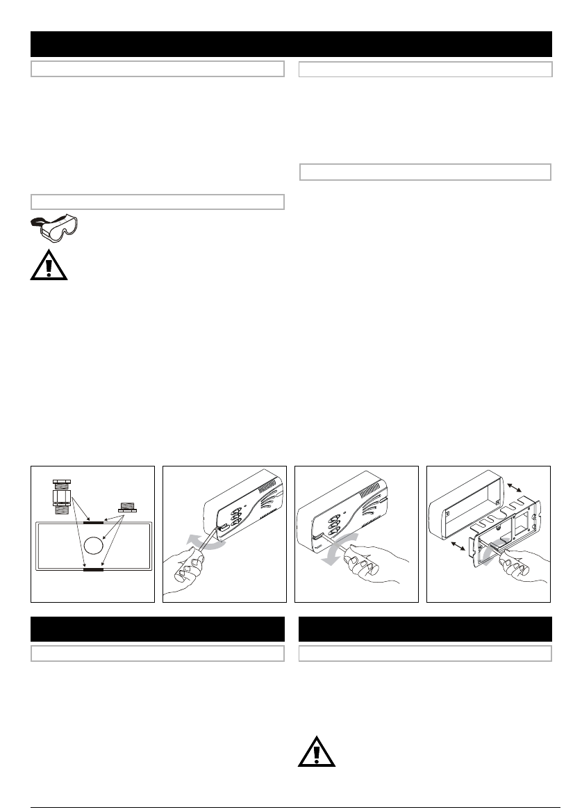
1 Detach the Fascia from the Mounting Frame by removing
the screw covers and two screws (Refer to Fig. 2a&b).
2 Detach the Mounting Frame from the Wall Box by
removing the two screws (Refer to Fig. 2c).
3 Lift the Wall Box away from the Plastic Surround.
4 Check that the electrical rating shown inside the controller
matches the power supply.
5 Disconnect the earth wire from the Wall Box.
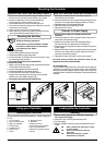
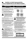
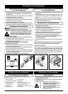
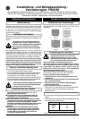
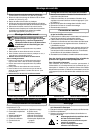
6 Make cable entry holes in the plastic and metal boxes by
removing suitable knockouts (Refer to Fig. 1).
Connect to Power Supply
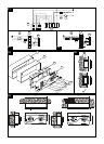
Fig. 1 : Cable Gland Positions
Fig. 2a : Removing screw covers Fig. 2b:Removing fascia Fig. 2c: Removing mounting frame
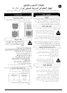
Cleaning
1 Before cleaning isolate the Controller completely
from the power supply.
2 Wipe the Cover carefully with a damp cloth.
3 Dry thoroughly.
4 Ensure ventilation slots are free from obstuctions at all
times.
♦♦
♦♦
♦
Never immerse the Controller in water
or other liquids.
♦♦
♦♦
♦
Never use solvents to clean the
Controller.
♦♦
♦♦
♦
Apart from cleaning, no other
maintenance is required.
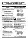
Looking after the Controller
Operating the Controller
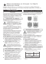
Using your Controller
1 On / Off switch
2 Intake / Extract switch
3 High / Low speed
4 Indicator light
5 Ventilation slots
6 Screw cover
7 Fascia
8 Mounting Frame
9 Wall Box
10Plastic Surround
11Controllers Terminal Block
12Fan’s Terminal Block
13Double Pole Isolator switch
14Fuses
The Controller has the following features: (Refer to diagrams
F1-F4).