


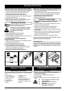
♦ A double pole isolating switch with a minimum contact
gap of 3mm (Wall or Ceiling mounted).
♦ Suitably rated 5-core cable to connect the controller to
the fan. If the fan is window mounted, use flexible cable
(Available from Xpelair).
♦ Suitably rated 3-core cable to connect the controller to
the Main Electrical Supply.
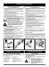
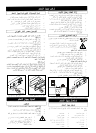
If using flexible cable, suitable glands
incorporating cable clamps must be fitted
to the knockouts in the Controller Box.
(Refer to Fig. 1).
These Instructions are for the Installation and Operation of the FR22/30 Fan Controller only. For Fan
Installation and Operating Instructions refer to literature provided with the appropriate fan.
♦♦
♦♦
♦ Not where ambient temperatures are likely to exceed
50°C.
♦♦
♦♦
♦ If installed in a kitchen the Controller must not be
mounted immediately above a cooker hood or eye
level grill.
♦♦
♦♦
♦ When intended for use in possible chemical corrosive
atmospheres, consult our Technical Service
Department (Outside the UK contact your local Xpelair
distributor).
♦♦
♦♦
♦ If installed in a shower room or bathroom the
controller and isolating switch must be situated so
that they cannot be touched by persons making use
of the bath or shower.
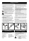
This appliance is designed to control the operation of Xpelair
fans of the GX9, GX12, WX9, WX12, RX9 & RX12 ranges
(wall & window mounted). The controller may be either surface
mounted, or recess mounted within it’s own patress box. You
may only wire one fan to each controller.
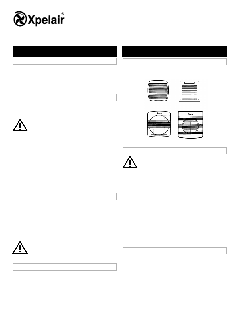
For the purpose of these instructions current and previous
versions of the fans are identified into Type A & Type B, as
follows:
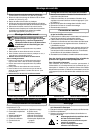
If wiring to Type A fans
A link is fitted between terminals 2 and 3 in the fan socket,
this must be removed before connecting the Controller.
If you do not remove it, the Controller will be permanently
damaged.
If wiring to Type B fans
There is no wire link to be removed.
If the fan is already installed
1 Ensure the power supply is isolated.
2 Disconnect the mains connections from the fan’s
terminal socket or from the terminal block.
3 Remove the existing wiring and make it safe.
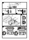
1 Route the 5-core cable from the Fan to the Controller
position.
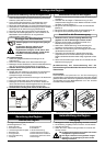
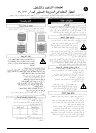
2 Wire one end of the cable into the fan connections as
shown thus:
3 Leave the other end ready to be connected to the
Controller.
Type A1
Type A2
Type B1
Type B2
Location of the Controller
Wire the fan electrical connections
Description
What the installer will need
Identifying Fan Type
Preparing the Fan
General Information Working with the Fan
If the fan is not yet installed.
1 Check that the fan electrical rating matches the power
supply.
FAN TYPE
F1
F2
F3
DIAGRAM
Type A1
Type A2
Type B
Table 1.
If wiring to an existing installation
isolate mains supply and remove applicable
fuses prior to any electrical procedure.
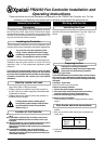
FR22/30 Fan Controller Installation and
Operating Instructions
These installation instructions are for the installation of the
controller when used in combination with Xpelair supplied fans.
The controller must be installed to fixed
wiring. Ensure the Main Electrical Supply
matches the rating shown on the controller
casing.
This appliance must be earthed.
All installation must be supervised by a qualified electrician.
Installation and wiring must conform to current IEE wiring
regulations (UK), or local appropriate regulations (other
countries).
If you have any queries either before, during and after
the installation of the controller, please do not hesitate
to contact the UK Xpelair hotline (number on back page).
Customers outside the UK: contact your local Xpelair
distributor.
Installing the Controller