9
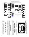
4) The Monitor Terminal Board: The
wiring for battery monitoring terminates
here. The ribbon cable from the meter
plugs into this board. It also has a RJ-45
jack on it for the Ideal Regulator Module.
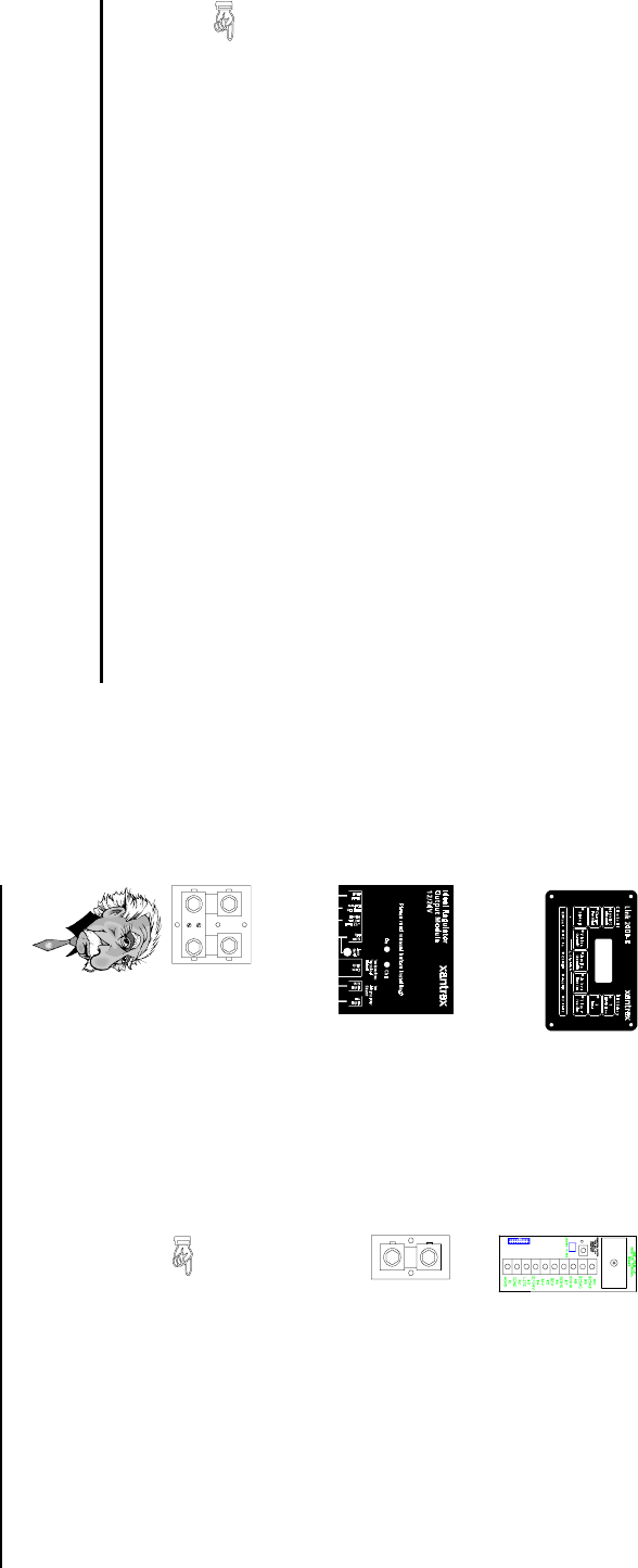
1) The LINK 2000-R
Meter: Contains the micro-
processor and display. The
actual regulation program is
in the meter. It is terminated
with a ribbon cable. It also has
a RJ-11 jack for the remote
cord to the inverter/charger.
WIRING INSTRUCTIONS
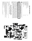
Refer to the wiring diagram while using these instructions.
There are several components to LINK 2000-R METERS:
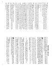
2) The Ideal Regulator
Output Module: Supplied
with a harness that connects
to the alternator. There is
also a RJ-45 jack and plugs
for the alternator shunt wiring
and red and green indicator
lights used for trouble-
shooting.
3) The Battery Shunt: Dual
500 A, 50 mV shunt used to
measure current flowing in or
out of the batteries.
5) The Alternator Shunt: Single 500 A,
50 mV shunt used to measure current
flowing out of the alternator.
6) Four Conductor Remote Cord: This 25' long
phone cord connects the LINK to the inverter/charger.
This is the smaller of the two cords.
7) Eight Conductor Data Cord: This 25' long cord
connects the Monitor Terminal Board to the Ideal
Regulator Output Module. This is the larger of the
two cords.
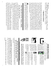
Our Customer Service Manager says, "Be a genius—ensure a
successful installation by following our wire-by-wire instructions
and please do the two progress checks and the final startup test."
Be sure the battery shunt is installed before proceeding.
MONITOR BOARD INSTALLATION & WIRING
MOUNTING THE MONITOR TERMINAL BOARD
The Monitor Terminal board should be secured behind or adjacent to the meter. It
should be accessible and easy to see during hookup. The meter comes standard with an
18" ribbon cable.
Wiring is simplified by using our custom multiple conductor twisted pair cable
available from your dealer. See LINK 2000 manual. If you supply your own cable we
recommend 16 AWG. Larger wire is okay but not necessary. Do not use larger than #14
AWG, as it will make terminating the wires difficult. Use twisted pairs where specified. Use
the same color scheme as on the schematic to facilitate troubleshooting if required.
Begin hooking up from the bottom (terminal #1 ) of the terminal strip toward
the top.
These two cords are not interchangeable.
i4.40
12
TERMINAL #10
YELLOW WIRE (B2SHB), is connected to the SMALL SCREW ON THE
BATTERY SIDE of the Battery #2 shunt (B2SHB). The TERMINAL #10 YELLOW
WIRE and TERMINAL #9 BROWN WIRE should be a twisted pair.
PROGRESS CHECK #2
Now it is time to check the battery current function. Plug the meter's ribbon cable into the
Monitor Terminal Board and/or insert the fuses. Turn off all DC loads and charging sources.
With everything off select Battery #1 or #2 Amps—the LINK 2000-R should read 0.0,
-0.0, or no more than -0.1 A. (The meter uses less than 0.1 A.) If there is a larger current
draw it normally means that not all the DC loads are turned off. There may be an alarm
system, a clock, or other instrumentation that is left on all the time intentionally. That is
okay as long as you find each load and decide that it is an acceptable continuous current
draw. Once your base-line current is known, remember it. If you cannot always turn off loads
and reach the same number of amps you should find out why. Turn on various loads and
make sure there is a minus sign in front of the display which indicates discharge. If the
number has no minus sign and there are no charging sources on, it means that the battery
shunt sense leads are reversed. If you have a problem call your dealer or Xantrex
Technology Inc. The wiring is now complete and the battery monitoring functions of the
meter now are fully operational.
The battery monitoring and inverter/charger functions of the LINK 2000-R may be
operated independently of the alternator regulator functions. Simply unplug the 8 conductor
data cord (described in the next section) between the Monitor Terminal Board and the Ideal
Regulator Output Module to disable the regulator. The alternator will freewheel harmlessly.
IDEAL REGULATOR OUTPUT MODULE WIRING
MOUNTING THE OUTPUT MODULE
The Ideal Regulator Output Module may be located anywhere convenient to the
alternator that is not subject to salt or fresh water spray. The components in this module
have been coated to resist corrosion but are not immune to, nor warranted against, abuse.
This module has on it the FET (field effect transistor) that actually does the work of
supplying power to the alternator field. While the reliability of this module is very high
it also does all of the real work. The system has been designed with on-site repairability
in mind, a spare Output Module or a standby regulator should be considered for long-
distance cruising.
The harness that is supplied with this module is a standard alternator harness. It
is keyed so that it cannot be improperly plugged into the module. The colors mentioned
below correspond to the color code of the wiring harness. There is also a 25-foot 8
conductor data cord supplied to interconnect the Monitor Terminal Board and the Ideal
Regulator Output Module. The following discusses each of the wires connected to the
Ideal Regulator Output Module beginning from the left side of the module.


