


8
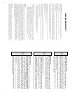
REQUIRED READING
1) Read the REQUIRED READING section of the LINK 2000 owner's manual.
2) All wiring to the terminal board should be #16 AWG (#14 may be used).
3)
The same 8 wire twisted pair cable recommended in the LINK 2000 manual may
be used for the LINK 2000-R. The wiring diagram is color coded to this cable.
CAUTION! YOU MUST READ THIS SECTION!
4) The LINK 2000-R Ideal Regulator Output Module is designed to replace external "P"
type regulators. If your alternator is internally regulated, modification will be necessary. The
LINK 2000-R is
not designed to regulate N-type alternators; that is, alternators that require
regulation by switching in the negative supply to the field. This includes most Japanese and
internally regulated alternators. If these alternators are to be converted to external regulation
you must disconnect the internal regulator and the diode trio in the alternator. This
should be performed by a qualified alternator shop. The warranty does not cover the
alternator, batteries, or any other devices, or equipment in the system.
An
improperly converted alternator may cause damaging high voltages. Please be sure
to check the regulation voltage during initial operation to verify that the LINK 2000-R
is in control of the system.
5) The LINK 2000-R is designed to regulate alternators up to 230 amps, provided that
the field current does not exceed 10 amps total. It can also regulate two alternators in parallel,
charging the same battery, if they are the same size with a combined total capacity of less
than 230 amps, and combined field current less than 10 amps. If the alternators are on
different engines you must install a normally open oil pressure switch, or a relay activated
by the key switch, in series with the field of each alternator to avoid supplying field current
to an alternator whose engine is not running.
6) The alternator shunt is in series with the alternator output and carries the full alternator
current. The brass portions of the shunt are at +12 V (24 V) potential and should therefore
be protected from accidental contact to grounded objects or battery negative.
7)
If a small alternator is being replaced by a high output alternator you must increase
the size of the alternator wiring. Use the table below to find the appropriate wire size. The
total length of both the positive and negative runs must be measured.
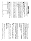
ALTERNATOR MAXIMUM OUTPUT CABLE SIZE (AWG)
10 FT OR LESS 11 TO 20 FT
35 A #8 #8
60 A #6 #4
75 A #6 #4
100 A #4 #2
130 A #4 #1
170 A #2 #1/0
200 A #1 #2/0
8) Battery temperature should never exceed 120 °F. We recommend a 110 °F limit.
13
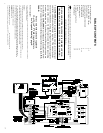
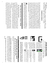
FIELD WIRE TERMINAL
BLUE WIRE is connected to the FIELD TERMINAL on the back of the alternator
and supplies alternator field current. The gray insulated plug connector may be plugged
directly into standard small case high output alternators. (NOTE: The white wire that is
stubbed out of the gray plug is for electronic tachometers and has no function related to
alternator regulation.) If the plug will not fit into the alternator it may be cut off and the blue
wire may be terminated with an insulated spade terminal or other appropriate connection
for the alternator field terminal on the alternator. (The RED LED, on the Ideal Regulator
Output Module, labeled CHG indicates field voltage is present on this BLUE WIRE. The
RED LED glows more brightly as the alternator output increases.)
CAUTION: The gray plug will fit into the typical DELCO internally regulated
alternator but the internal regulator must first be disabled. DO NOT attempt to use the
Link 2000-R with an internally regulated alternator without modifying it to use
external regulation! See #4 on page 8.
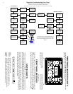
REG ON TERMINAL
BROWN WIRE supplies the voltage that turns on the Ideal Regulator Output
Module. It should be connected to a normally open oil pressure switch, or some other
switch (such as an ignition switch or relay), that is hot (+12 V / 24 V)
when the engine is
running and off when the engine is off. If the system has a battery isolator, or separate
engine starting battery, the BROWN WIRE should be supplied from a stable 12 V / 24 V
source. This wire must not be connected to the oil pressure sensor for the oil pressure
gauge or to the oil pressure switch for the alarm system. A separate
NORMALLY OPEN
oil pressure switch should be used. When this wire is energized the GREEN LED labeled
ON is lit.
The GREEN LED must be OFF when the engine is off! If the regulator is left
continuously ON it may destroy the Ideal Regulator Output Module, damage the
alternator, discharge the battery, and cause system failure.
+12 V/24 V TERMINAL
RED WIRE is the +12 V / 24 V supply. It is shown connected to the alternator
side of the alternator shunt (ASHA). Connecting it here ensures a stable voltage with little
voltage drop to supply the alternator field power. The 10-amp fuse shown should be
installed to protect the wiring.
If an isolator is in the system, the +12 V / 24 V (Red wire) must connect to the
battery side of the isolator.
GND (GROUND) TERMINAL
BLACK WIRE wire is power ground. It is connected to the alternator ground.
ASHB TERMINAL (alternator shunt battery side)
GREEN WIRE must be terminated on the small screw on the battery side of
the alternator shunt. This wire must be connected exactly as shown. Since this wire is
at battery voltage it should be protected with a 2-amp fuse
at the shunt as shown;
install the fuse after the wiring is connected. No other wires should be connected here.