7
SPECIAL SETUP FOR LINK 2000-R
The following is a list of special setups that may be necessary to tailor the LINK 2000-R to
your system. Please see pages 10–14 of the LINK 2000 Owner's Manual for details on
how to use the FUNC mode.
F10 - ALTERNATOR CURRENT LIMIT
DEFAULT = 100 RANGE = OFF, 30–220 AMPS STEP = 10 A
This function is only used with the Link 2000-R (Alternator Regulator Model). It sets
a safety current limit for the alternator. This limits the maximum amount of current that the
alternator can deliver which in turn reduces heat and wear on belts and bearings. This value
is reset to 100 amps in the event of a reset to factory default values.
CAUTION: OFF defeats this safety feature and the alternator will be run at
full output until the Acceptance Voltage is reached. You can also use this feature
to troubleshoot the alternator current measuring/limiting feature.
F11 - BATTERY #2 USED FOR CONTROL
DEFAULT ON = BATTERY #2 USED FOR CONTROL
OFF = BATTERY #2 IS NOT USED FOR CONTROL
This function is used to defeat Battery #2 as a part of the charger and alternator
regulator control functions of the Link 2000-R. This is necessary for systems that have
both 12 V and 24 V batteries. Battery #1 must be the battery that is used by the Freedom
Inverter (or charged by the alternator when controlled by the Link 2000-R). You may also
wish to use this function if the main house battery (Bank #1) is substantially larger than
a separate engine battery (Bank #2) that is also monitored by the Link 2000-R. This will
prevent the Link 2000-R from making a premature transition to float based on the smaller
engine battery meeting the charged parameters substantially before the house battery.
NOTE: Function F11 is not changed in a reset to factory default values. If you
wish to change this function you must use the setup routine to change it.
14
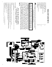
ASHA TERMINAL (alternator shunt alternator side)
YELLOW WIRE must be terminated on the small screw on the alternator side of
the alternator shunt. This wire should be connected exactly as described to ensure proper
operation. Since this wire is at battery voltage it should be protected with a 2-amp fuse
at
the shunt as shown; install the fuse after the wiring is connected. No other wires should be
connected here.
FINAL TEST AND ENGINE STARTUP
Do this test with the engine OFF!
If you cannot pass this test do not start the engine!
This is the final checkout. Plug the 8 conductor data cord (the larger of the two
phone cords) into the Monitor Terminal Board and the Regulator Output Module. Check
the battery amps—you should see the same low number as in PROGRESS CHECK #2.
The green ON LED on the Ideal Regulator Output Module must be off.
Now we want to simulate the engine running, so turn on the regulator by turning the
key switch to the ON position, or if normally open oil pressure switch is used, jumper
together its two terminals.
For this test only we want to supply voltage to the REG ON
terminal while the engine is off. The GREEN ON LED should be ON. The red Charge Cycle
Status light on the Link 2000-R front panel should also be ON. The RED CHG LED on
the Output Module, which indicates that field voltage is being supplied, should gradually
increase in brightness during the next 30 seconds. Also check the TIME function
which should display "a000" indicating the alternator output current is zero.
To verify that current is actually flowing into the alternator field use the LINK
2000-R to check the number of amps flowing from whichever battery has been selected
by the main battery switch. You should see -3 to -5 amps of current flowing. This current
is being supplied to the alternator field, and perhaps, to other instrumentation that is also
turned on with the key switch if you are not using an oil pressure switch.
To verify that it is the alternator field consuming the current, turn off the power
to the REG ON terminal and disconnect the FIELD wire from the alternator field. Repeat
the test. The current should now be about 2 to 4 amps less than it was. This test assures
you that the regulator is supplying the field current.
Another easy way to test if the field is energized is to check the magnetism of the
rotor by touching the end of the alternator shaft with a steel screwdriver. Do it with the
regulator turned on (wait 20 seconds for ramp-up cycle) and with it turned off—there
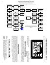
should be a noticeable difference. If you cannot pass this test see the troubleshooting
flow chart. If you still need help, call your dealer or Xantrex Technology Inc.


