


8
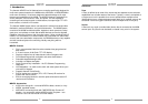
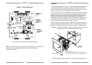
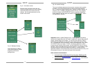
Figure 2.1: T568A and T568B Wiring Standard
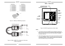
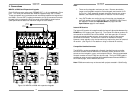
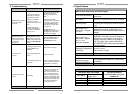
Figure 2.2: MX88 – MRKP2 Pin-out diagram for Cat-5 cable
(T568B configuration)
Wire Color Pin # Signal
white/orange 1 485 +
orange 2 485 -
white/green 3 12V RET
blue 4 IR RET
white/blue 5 IR
green 6 +12V
white/brown 7 Attn. 485
brown 8 IR Loop Back
Cat 5
Cable
RJ45 Connector at
Controller/Amplifier
RJ45 Connector
at Keypad
Wire Color Pin # Signal
white/orange 1 485 +
orange 2 485 -
white/green 3 12V RET
blue 4 IR RET
white/blue 5 IR
green 6 +12V
white/brown 7 Attn. 485
brown 8 IR Loop Back
9
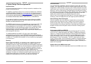
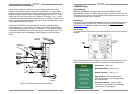
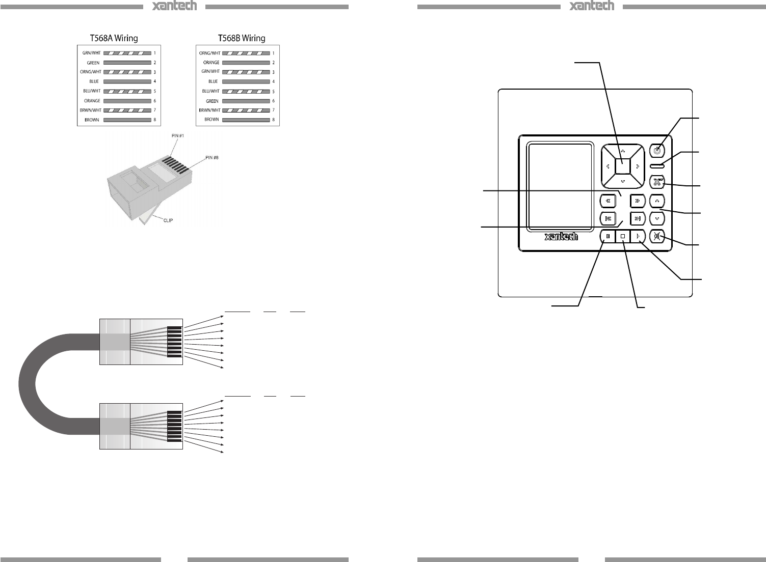
MRKP2 – FRONT PANEL
Figure 2.3: MRKP2 Keypad layout and Main display
Notes:
• Tone Control functions of the MRKP2 can be entered by pressing the
Next arrow once inside a source control page. Please note that each of
the three controls can be returned to their center position by tapping
the center of each bar.
• Unlike older keypads, and due to the unique and streamlined functional
set-up of the MRKP2E’s buttons, “press-and-hold” tier 2 functions are
not supported. However, Tier 2 button IDs and the macros underneath
them are available through Universal Dragon.
NAVIGATION BUTTONS
UP, DOWN, LEFT, RIGHT,
ENTER/SELECT (center button)
POWER
ON/OFF
“
X
”
(
SETUP
)
VOLUME
UP/DN
MUTE
PLAY
STOP
PAUSE
TRACK SKIP
NEXT/PREV
SCAN
FWD/RRW
MAIN
DISPLAY
scan
skip
volume
INTERNAL IR
SENSOR