


MAINTENANCE
86037580 GLIDE 01/03/07
4-9
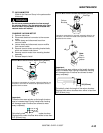
3. Locate release lever on top of brush or pad
driver. With finger rotate release lever against
spring pressure counter clockwise. Brush/pad
driver will release and drop down.
4. To reinstall, center the cut out of the release
lever plate on brush/pad driver to be installed
under the brush drive hub.
5. Raise brush/pad driver up until assembly
contacts brush hub. Rotate slightly until driver
engages release lever plate.
6. While holding upward pressure, rotate brush/pad
driver assembly clockwise. When fully engaged,
release lever plate will rotate under spring
pressure to lock assembly.
NOTE: Check that release plate is completely closed
and pad/brush is securely attached. Damage to
driver or brush could occur.
7. Repeat the procedure for the opposite side of
the machine.
8. The center brush should be changed from the
right side.
9. Reinstall the side squeegees.
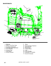
6. VACUUM FILTER
The vacuum filter is located inside the recovery tank.
The vacuum filter prevents debris from entering the
vacuum motor. Daily remove and clean filter of any
debris for maximum airflow.
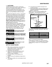
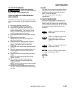
7. FLOAT SWITCH
The float switch is located inside the recovery tank.
The purpose of the float switch is to notify the user
that the recovery tank is full. When the float switch is
activated, the scrub brush motors and solution flow
will stop, the scrub deck will raise, the squeegee will
rise after 60 seconds, and the vacuum motor will
turn off 10 seconds later.
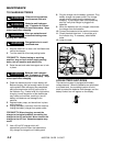
8. SOLUTION STRAINER
The solution strainer is located behind the right rear
wheel of the Glide. The solution strainer protects the
solenoid valve from debris. If there is little or no
solution flow to the ground, check the strainer for
debris. Drain the solution tank and clean the solution
strainer. To remove the strainer, turn the bottom part
of the strainer counterclockwise until the bottom is
separated. Clean out the debris from the wire mesh
and re-assemble. Make sure the O-ring gasket is in
place when re-assembled.
9. BRAKE
(Refer to Brake Group in the Parts section of the
manual).
The brake pedal and parking brake operate the self-
centering front wheel disc brake. The disc and
caliper should be inspected every 200hours of
operation for cracks and disc wear. The brake
should be adjusted so that the disc pads are as
close to the disc as possible, without causing brakes
to drag.
BRAKE ADJUSTMENT
FOR SAFETY: Before leaving or servicing machine,
stop on a level surface, turn off machine and remove
key.
1. Disconnect batteries from machine.
2. Turn the steering wheel fully to the left.
3. Locate the brake adjustment screw on the brake
caliper.
4. Loosen the lock nut.
5. Turn adjustment screw in until finger tight, then
back off 1/8 turn.
6. Hold adjustment screw and tighten lock nut.
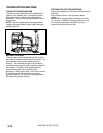
10. STEERING CHAIN TENSIONER
(Refer to Steering Group in parts section of manual).
The steering chain transfers power from the steering
shaft to the drive wheel, controlling steering
response. Check the chain condition and tension
every 200 hours of operation. Proper chain tension
is important to maintain steering response. The
chain should deflect 1/16 in. Use a light spray lube if
needed.
STEERING CHAIN TENSIONER ADJUSTMENT
1. Locate chain tensioner bolts.
2. To increase tension, tighten lock nuts retaining
chain tension plate.
3. To decrease tension, loosen lock nuts retaining
chain tension plate.
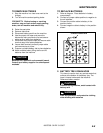
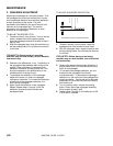
Icon appears on information screen 1 when
float switch is activated.