ADP
MAINTENANCE
INSTRUCTIONS
WARNING:
Removethe machine power
cord from the electrical source before
making any adjustments or repairs.
ONLY QUALIFIED MAINTENANCE PER-
SONNEL ARE TO PERFORM REPAIRS.
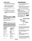
HANDLE LOCKADJUSTMENT
The black knob on the opposite end of the
rod from the adjusting lever controls the
tightness of the adjusting knob.
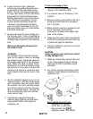
VAC SHOE
Remove the screws holding the parallel
arms to take off the vac shoe for repairs or
replacement.
When reinstalling the vac shoe be sure that
the wave washers are floating and not
pinched.
BRUSH ASSEMBLY AND BEARINGS
1.
Remove belt guard and roll belt off motor
pulley.
2. Tilt machine back on handle and remove
brush pulley guard.
3. Remove shaft retaining screws and
washers from each end of the brush shaft.
4. Replace brush or bearings as required.
TRANSPORT WHEELS
Remove screw and hub cap to service
wheel.
Before putting wheel back on clean axle and
apply a light coat of silicon lubricant.
SUPPORT ROLLER
1. Tilt machine back on handle.
2. Loosen lock nuts on each end of roller
axle and remove assembly.
3. Replace and repair as necessary.
4. Clean axle and apply a light coat of
silicon lubricant before reassembling.
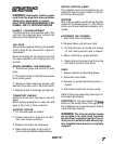
SWITCH CONTROL PANEL
The switches and circuit breakers are ac-
cessed through the panel located on the bot-
tom of the control panel.
CAUTION:
After making repairs use the wiring diagram
located on the access panel or in this manual
to be sure all wire leads are properly con-
nected.
ACCESSING THE CHASSIS
1. Drain both tanks completely.
2. Remove dome and recovery tank.
3. Tilt machine back on handle and remove
(4) nuts holding solution tank to chassis.
4. Return machine to upright position.
5.
Raise tank and remove hose from pump
inlet and set solution tank aside.
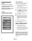
PUMP
1. Access chassis as described above.
2. Disconnect wire leads.
3. Remove (4) screws attaching pump to
chassis.
4. Disconnect hoses and remove pump.
Refer to the pump assembly drawing for in-
ternal parts and repairs.
CAUTION: Do not over-tighten the
hose-
barbs on the pump head. Over-tightening
the hosebarbs can cause the pump head to
crack and begin leaking.
WARNING:
The internal solution hoses
are encased in an outer hose to protect
the electrical component parts in the un-
likely event a solution hose should rup-
ture. Replace hoses exactly as originally
supplied.
98198
7/l/97
7


