


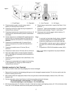
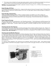
8. Position the furnace on the wall inserting the inlet/outlet flue in the hole previously drilled. Make sure that the edges of the
support bracket perfectly match the existing holes in the back on the unit (Figure 5)
9. Attach the furnace to the support bracket with the two screws provided. During this operation make all necessary
adjustments to have a correct installation of the unit (Figures 5 and 6)
10. Reinstall the external casing by tightening the relevant screws (Figure 3).
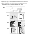
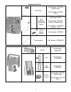
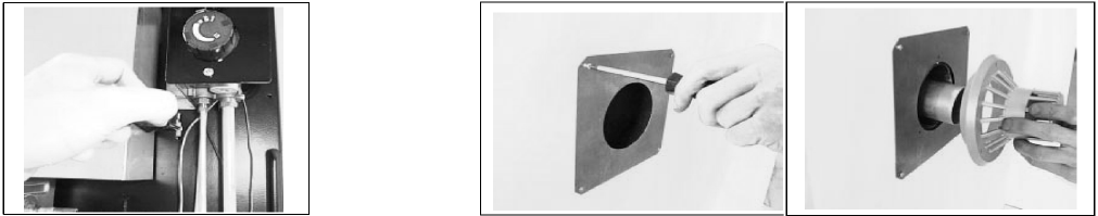
11. On the external side of the wall, install the protection plate in such a way that the center of the hole in the plate matches
the center of the hole in the wall. First place the plate in the right position and mark the holes on the wall. Then, remove
the plate and drill the holes in the wall. If the wall can receive self–tapping screws, drill 1/8-inch diameter holes. If not, drill
1/4-inch diameter holes and use the plastic anchors provided. Reposition the plate and fix it onto the wall with the four
screws provided. (Figure 7 - Left)
12. Mount the vent cap on the flue pipe and fix it onto the external plate with the three self–tapping screws provided. (Figure 7
- Right)
13. Connect the gas supply line. A gas tap just before each furnace must be installed.
14. Turn on gas supply and check for gas leaks with soapy water or other suitable means on all gas connections.
Figure 6
Figure 7
Gas Supply
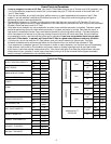
Check all local codes for requirements, especially for the size and type of gas supply line required. On natural gas lines less than
15” (380 mm) long, use 1/2” tube; on longer runs, use 3/4” iron tube or equal. On LP gas lines please consult LP Gas supplier.
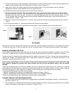
Installing a New Main Gas Cock
Each furnace should have its own manual gas cock. A manual main gas cock should be located in the vicinity of the unit. Where
none exists, or where its size or location is not adequate, contact your local authorized installer for installation or relocation.
Compounds used on threaded joints of gas piping shall be resistant to the action of LP Gas. The gas lines must be checked for
leaks by the installer. This should be done with a soap solution watching for bubbles on all exposed connections, and if
unexposed, a pressure test should be made.
Never use an exposed flame to check for leaks. Furnace must be disconnected from piping at inlet of control valve and
pipe capped or plugged for pressure test. Never pressure test with furnace connected; control valve will sustain
damage!
A gas valve and ground joint union should be installed in the gas line upstream of the gas control to aid in servicing. It is required
by the National Fuel Gas Code that a drip line be installed near the gas inlet. This should consist of a vertical length of pipe tee
connected into the gas line that is capped on the bottom in which condensation and foreign particles may collect.
The use of the following gas connectors is recommended:
– ANSI Z21.24 Appliance Connectors of Corrugated Metal Tubing and Fittings., CGA 6.10.
– ANSI Z21.45 Assembled Flexible Appliance Connectors of Other Than All–Metal Construction.
The above connectors may be used if accepted by the authorities having jurisdiction.
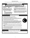
Pressure Testing of the Gas Supply System
1. To check the inlet pressure to the gas valve, a plugged tapping, accessible for test gauge connection, is provided on the
gas valve. (Figure 8 - A).
2. The furnace and its individual shutoff valve must be disconnected from the gas supply piping system during any pressure
testing of that system at test pressures in excess of 1/2 psig (3.5 kPa).
7