


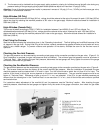
Installation
Installation should be done by a QUALIFIED SERVICE TECHNICIAN.
The furnace must be located on an outside wall.
Wall Installation
Minimum clearances from combustible materrials:
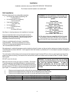
WARNING: For the installation of this furnace, the
following items must be used as a vent air intake
system:
• Unit to the top surface of carpeting, tile:
2-inches (50 mm)
• Unit to back wall (0” to spacers):
1/4-inch (6.3 mm).
External Plate
• Vent to wall enclosure:
(Part Number: WFL–STF088)
1-inch (25.4 mm)
External Vent Cap
• Unit to sidewalls:
(Part Number: WFR–12426530)
2-inches (50 mm)
Flanged Air Inlet Tube
• Unit to ceiling:
(Part Number: WFR–12476500)
10-inches (254 mm)
Air Tube Gasket
(Part Number: WFC–12900128)
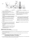
See Figure 1 showing clearance for installation of vent cap.
Flue Outlet Tube
(Part Number: WFR–12476510)
Leave at least three feet in front of the wall furnace for
servicing and proper operation. The wall furnace must be
(All the above items are supplied with the furnace)
installed in such a way that the external casing can be
completely removed for servicing.
The diameter of the hole in the wall must exceed at
least 2-inches (50 mm) the diameter of the air inlet tube.
If there is a shelf above the furnace, it must be be
noncombustible. A minimum clearance of 4-inches
(100 mm) is recommended between the furnace and
the noncombustible shelf above it.
Gas equipment in residential garages must be installed so that all burners and burner ignition devices are located not less than
18-inches (460 mm) above the floor. Such equipment shall be located, or protected, so it is not subject to physical damage by a
moving vehicle.
The vent terminal of this direct-vent furnace must be located at least 9-inches (230 mm) from any opening through which flue
gases could enter a building. The bottom of the vent terminal and the air intake must be located at least 12-inches (300mm)
above grade.
DO NOT cover the furnace.
WARNING: The nearest point of the vent cap should
be a minimum horizontal distant of six (6) feet (1,830
mm) from any pressure regulator. In case of
regulator malfunction, the six (6) feet (1,830 mm)
distance will reduce the chance of gas entering the
vent cap.
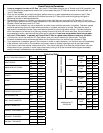
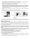
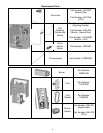
Make sure that the correct gas supply is available. Conversion
To another gas type must be performed by a qualified service
technican. If the type of gas does not correspond to the type to
be used (natural or LP Gas), it must be converted to the correct
type of gas. It is necessary to do the following two operations:
1. Remove and change the pilot orifice with the correct gas type as shown below.
2. Remove and change the burner orifice with the correct gas type as shown below.
3. Remove and change the gas valve with the correct gas type as shown below.
Gas Type Orifice Part Numbers Gas Valve
Natural Burner Orifice: JGLL051; Pilot Orifice: JGLL064 JVLV023
Propane (LP Gas) Burner Orifice: JGLL070; Pilot Orifice: J12160880 JVLV024
4