


Servicing
All servicing activities must be carried out by a qualified service technicial or a service agency. The home owner may not
service the furnace. The home owner must read this section to be informed of the periodic maintenance and checks the
required. All servicing (except on vent system) must be carried out with the external casing removed. After any servicing, the
external casing must be reinstalled properly.
Checking and Adjusting the Gas Manifold Pressure
The furnace comes set from the factory at the correct HI and LO gas manifold pressures as shown in “Technical Data”. It is
recommended to check the pressures periodically (minimum once a year). If adjustment is required, this can be done by
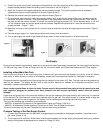
adjusting screws C and D. (Figure 8) A test gauge must be connected as explained in “Checking the Gas Manifold Pressure”.
Proceed as follows:
1. Place the unit on and in the HI mode (knob in HI position).
2. Adjust the HI pressure by turning the screw C (pressure regulator) to the value given in “Technical Data”. Turn clockwise
to increase the pressure, turn counterclockwise to decrease it.
3. Turn the control knob clockwise until the gas control switches to LO mode. The position in which this occurs depends on
the actual room temperature.
4. Loosen screw D until the correct value for the LO pressure is achieved. Turn clockwise to decrease the pressure, turn
counterclockwise to increase it.
5. Switch the unit from LO to HI mode to check that both the HI and LO pressures are correct. A tolerance of plus or minus
0.1-inches w.c. on the pressure value is acceptable. Readjust if needed.
6. Disconnect the test gauge and tighten firmly the screw of the gauge connection, then check for gas leaks from it.
The HI and LO pressures must be adjusted in the way explained above. Never try to adjust them independently from each other.
Checking, Removing and Reassembling of the Vent Air Intake System
It is essential that the vent air intake system is examined periodically (minimum once a year) to verify it is clean from dust and
deposits of solid materials such as leaves or nests. The vent air intake system is checked from outside. Proceed as follows:
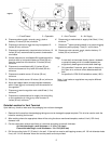
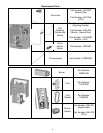
1. Remove the vent cap by removing the three outer screws. (Figure 7)
2. Remove the inner flue pipe. Do not use tools; the pipe can be extracted by hand.
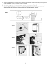
3. Remove dust and desposits from the vent cap and flue pipes. Deposits in the air pipe must be taken outside. Do not
push them inside the furnace. The outer air pipe may not be removed from outside.
4. Reinstall the flue pipe from outside. Do not use glue or sealants.
5. Reinstall the vent cap on the flue pipe. Do not use glue or sealants. Tighten the three outer screws.
Lubrication of Moving Parts
This furnace does not require lubrication. Do not try to lubricate any part of the furnace such as motors bearings, keys, knobs,
screws, etc.
Flame Visual Check
Correct and proper operation of the burner may be checked by examinng the burner flame. The flame may be examined
through the front flame viewer. The flame must be stable and have blue color. Some small yellow tips are acceptable with
propane gas. If the flame is yellow or has excessive turbulence, check the gas manifold pressure and the vent air intake system.
If all these are acceptable, call a qualified service technician for a complete check of the furnace. Call also your gas supplier to
check the composition of the gas in use.
10