


6
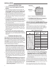
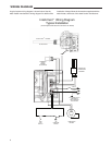
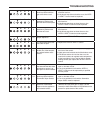
A typical system wiring diagram is shown below. Use the
water heater manufacturer’s wiring diagram for details of the
installation. Always follow the instructions supplied with the
water heater, and those of the water heater manufacturer.
HIGH
LIMIT
SWITCH
AIR
PRESSURE
SWITCH
COMBUSTION
BLOWER
BLACK
WHITE
GREEN
TO POWER SUPPLY
DISCONNECT
AND OVERLOAD
PROTECTION
IGNITOR AND
FLAME PROBE
ASSEMBLY
INSET
Intelli-Vent
™
Wiring Diagram
Typical Installation
(Consult Appliance Manufacturer's Instructions For Details)
BOTTOM VIEW
INTELLI-VENT CONTROL
TM
FLAMMABLE
VAPOR
SENSOR
(IF EQUIPPED)
WIRING DIAGRAM