


3
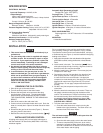
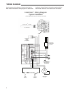
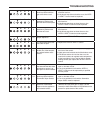
GROUND JOINT UNION
INTELLI-VENT™
CONTROL
GAS SUPPLY
PIPE
TEE
DRIP LEG
(SEDIMET TRAP)
3" MINIMUM
(MANDATORY)
PIPE CAP
SHUT-OFF VALVE
d. Check all new water piping for leaks. Repair as needed.
8. Open the gas shutoff valve.
9. BEFORE TURNING ON THE APPLIANCE, CHECK THE
GAS LINES FOR LEAKS.
a. Use a soapy water solution. DO NOT test for gas leaks
using a match or open flame.
b. Brush the soapy water solution on all gas pipes, joints,
and fittings. Use care that excess solution does not
enter the control’s plastic housing.
c. Check for bubbling soap. This means you have a leak.
Turn OFF the gas and make the necessary repairs.
d. Turn on the gas and recheck for leaks. Repeat this
process until you are sure the system is gas-tight. If
repeated work on a part does not stop the leak, the
part must be replaced.
e. Rinse off the soapy solution and wipe all the plumbing
parts dry.
INSTALLATION
CAUTION
!
Never use this water heater unless it is completely
filled with water. To prevent damage to the tank, the
tankmustbelledwithwater.Watermustowfrom
the hot water faucet before turning ON gas to the
water heater.
Figure 1. Typical gas connection
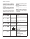
PRESSURE REGULATOR ADJUSTMENT
These controls are shipped from the factory with the regulator
set as specified on the control label. Consult the appliance
rating plate to ensure burner manifold pressure is as specified.
If another outlet pressure is required, follow these steps.
If a valve has been factory-adjusted for the 2.5 to 5 inches
W.C. range, it cannot be field-adjusted outside that range.
1. Turn off all electrical power to the system
2. These models have 1/8 NPT threaded taps. The outlet
pressure tap plug will need to be removed and a separate
hose fitting installed.
3. Attached a hose and manometer to the separate hose
fitting which has been installed in place of the 1/8 NPT
threaded tap.
4. Turn on system power and energize valve.
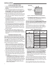
5. Remove regulator cover screw and turn regulator adjust
screw clockwise (
) to increase pressure, or
counterclockwise ( ) to decrease pressure (see
NOTE
fig. 3). Always adjust regulator to provide the correct
pressure according to the original equipment manufacturer’s
specifications listed on the appliance rating plate. Replace
regulator cover screw.
6. Turn off all electrical power system to the system.
7. Remove manometer hose from outlet pressure tap.
8. Remove hose fitting and re-install the 1/8 NPT pressure
tap plug. Tighten to 60 in-lb max.
9. Turn on electrical power to the system.
10. Turn on system power and energize valve.
11. Using a leak detection solution or soap suds, check
for leaks at pressure boss screw or pressure tap plug.
Bubbles forming indicate a leak. SHUT OFF GAS AND FIX
ALL LEAKS IMMEDIATELY.
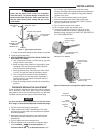
Outlet Pressure
Regulator Adjust
Tower
1/8 Threaded Outlet
Pressure Tap
37E Intelli-Vent™ Control
36G Valve
Outlet Pressure
Regulator Adjust
Tower
1/8 Threaded Outlet
Pressure Tap
Figure 2. Pressure port and regulator adjust locations
Regulator
Cover Screw
Plastic
Adjust Screw
Regulator
Spring
Figure 3