


2
SPECIFICATION
ELECTRICAL RATINGS:
Input and Frequency: 120 VAC, 60 Hz
Output Ratings:
Ignitor Load: 2 Amps maximum
Inducer Draft Motor: 3 Amps Full Load, 4 Amps Locked
Rotor
Current: 0.2 Amps @ 120 VAC
Range of Regulation (Btu/Hr)
Minimum: 30,000 Maximum: 150,000
Pressure Regulator Setting: Factory set to 3.5” or 4.0” W.C.
Adjustable 2.5” to 5.0” W.C.
1.0” Pressure Drop Capacity
a
100,000 Btu/Hr
a
Based on 1000 Btu/ft
3
, 0.64 specify gravity natural gas
Maximum Inlet Pressure: 1/2 PSI maximum
Ambient Temperature Rating:
32
o
F to 160
o
F (0
o
C to 70
o
C )
Automatic High Temperature Cutoff:
Single-Use Type, 185
o
F(82
o
C)
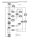
Prepurge Time: 5 Seconds
Ignitor Warm-up Time: 20 Seconds
Trial for Ignition Period: 4 Seconds
Inter-purge Time: 5 Seconds
Post-purge Time: 5 Seconds
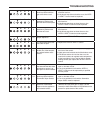
Ignition Retries: 2 Retries; 3 Trials before lockout
Ignition Recycles: 2 Recycles, 3 Losses of flame before
lockout
BODY CONFIGURATION:
Right angle with a 1/2” NPT inlet and a 1/2” inverted flare
outlet
MOUNTING:
Limited Horizontal/Vertical
INSTALLATION
1. This control must be installed or serviced only by a
professional.
2. For your safety, this control is supplied with tamper
resistant screws. Do not attempt to repair or adjust
the control. If you experience problems, replace the
control immediately. Continuing to use a damaged
control could result in fire and/or explosion.
3. An odorant has been added to the gas to help you
detect it. Before lighting, search for the odor of gas by
snifngatoorlevelaroundthewaterheater.
4. In some situations, the gas may lose its odor. To
detect unodorized gas, you must have a gas detector,
which can be purchased from your gas company. If
you do not have a detector and have the slightest
suspicion that gas may be present, get out of the
house and call the gas company. DO NOT RELY
TOTALLY ON YOUR NOSE.
REMOVING THE OLD CONTROL
1. Shut off the gas to the water heater
2. Turn off electrical power to the water heater.
3. Remove the two plastic wire connectors that plug
into the bottom of the control. The connectors have
latches which must be depressed. DO NOT FORCE
THE CONNECTORS, DAMAGE TO THE WIRING MAY
RESULT.
4. Shut off the water at the cold water inlet.
5. Connect a hose to the water heater drain cock. Drain the
water to a nearby drain. Open a hot water faucet for faster
draining.
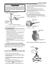
6. Disconnect the gas line at the union (Figure 1). Remove
the piping from the old control.
7. Remove the control by turning it counterclockwise ( ).
INSTALLING THE NEW CONTROL
All piping must comply with local and state ordinances or
with the National Fuel Gas Code (ANSI Z223.1-NFPA 54),
whichever applies.
NOTE
Dirt or contamination in the gas line can block the control
from operating creating a risk of explosion, injury, or death.
To protect the control from dirt and contamination, a drip leg
or sediment trap (see Figure 1) must be installed in the piping
leading to the control.
1. Apply pipe compound to the male threads of the pipe that
goes into the control, leaving the first two or three threads
clean.
2. Install control in the tank. Turn clockwise (
). Use a
short piece of pipe to help in turning. Align the control so
that the burner tube may be connected.
3. Make the main burner connection. Do not use pipe joint
compound or Teflon tape.
4. Connect the gas line. Use new black iron pipe that has
been properly reamed. If old pipe is used, be sure it
is clean and free from rust and scale. Use pipe joint
compound on male threads only. (Use pipe joint compound
approved for natural and LP gas service.) Do not use
TEFLON tape. Do not apply compound to the first two
threads.
5. DO NOT use joint compound or tape on the union
connection.
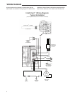
6. Make the electrical connections to the control. There are
two plastic connectors that plug into the bottom of the
control. The connectors are “keyed” so that they can only
be inserted one way. Make sure that the connectors
are properly aligned before attempting to insert. DO
NOT FORCE THE CONNECTORS; DAMAGE TO THE
CONTROL WILL RESULT.
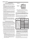
7. To fill the water heater with water:
a. Close the water heater drain valve by turning the
handle to the right (clockwise). The drain valve is on
the lower front of the water heater.
b. Open the cold water supply valve to the water heater.
c. To ensure complete filling of the tank, let air exit by
opening the nearest hot water faucet. Allow water to
run until a constant flow is obtained. This will let air out
of the water heater and the piping.
NOTE
The cold water supply valve must be left open when the
water heater is in use.