


_____________________________________INSTALLATION______________________________________
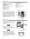
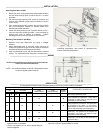
Attaching Sub-Base to Wall
1. Route wire from cooling equipment to thermostat location
and pull wires through hole in wall so that 6 in. of cable
protrudes.
2. Pull wires through opening near center of sub-base and
connect wires beneath proper terminal screws as shown
under “wiring”.
3.
Push excess wire into wall or switch box and plug up hole
with non-combustible material to prevent drafts from
affecting thermostat operation.
4.
Fasten sub-base loosely to wall in position shown in Fig. 1
using two mounting screws provided. Level sub-base by
placing spirit level on bottom of sub-base. Tighten
mounting screws to secure sub-base in level position.
Mounting Thermostat to Sub-Base
1. Remove cover from thermostat by pulling it straight
outward.
2. Attach thermostat base to sub-base, being sure that all
screws are tightened snugly since they serve as electrical
connections between thermostat and sub-base.
3. Snap on thermostat cover and set thermostat to desired
setting. The thermostat scale range has numbers from 1
through 5. The number “1” represents the cooler
controlling temperature, and number “5” represents the
warmer controlling temperature.
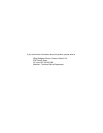
________________________________________WIRING_________________________________________
All wiring should be done according to local and national
electrical codes and ordinances.
NOTE: See Instruction Sheet on 8A18Z-1 Evaporative Cooler
Control for typical system hook-up.
______________________________________OPERATIONS______________________________________
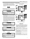
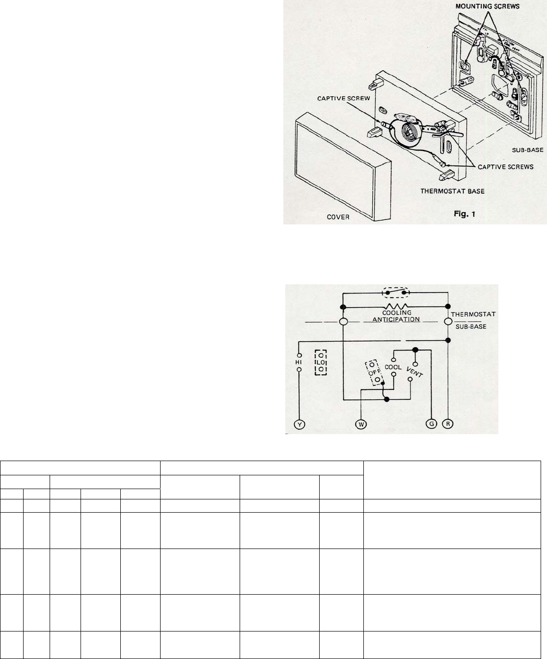
The chart below illustrates system and thermostat function during various modes of operation.
SUBBASE SWITCH POSITIONS SYSTEM FUNCTIONS
FAN SYSTEM
HI LO OFF COOL VENT
FAN
TIMER RELAY
FAN
SPEED RELAY
PUMP
RELAY
COMPONENT OPERATION
○ ● ●
NO FAN-NO PUMP-NO COOL
● ● ● ●
COOLING MODE-Pump relay and fan timer
relay energized by thermostat. Water begins
circulating on cooler pads, fan will start on low
speed after a short time-delay.*
● ● ● ● ●
COOLING MODE-Pump relay and fan timer
relay energized by thermostat. Fan speed relay
is energized by fan switch in “HI” position.
Water begins circulating on cooler pads, fan will
start on high speed after a short time-delay.*
● ● ● ●
VENT MODE-Fan timer relay energized by
thermostat. Fan speed relay is energized by
fan switch in “HI” position. Fan will start on high
speed after a short time-delay.
● ● ●
VENT MODE-Fan timer relay energized by
thermostat. Fan will start on low speed after a
short time-delay.*
● Indicates switch position on thermostat sub-base and
system function in operation.
○ If left in “HI” position-no Fan, but fan speed relay will
remain energized.
*
Fan timer relay energized in approximately one minute. When system
shuts off, it opens in approximately ½ minute.