


7
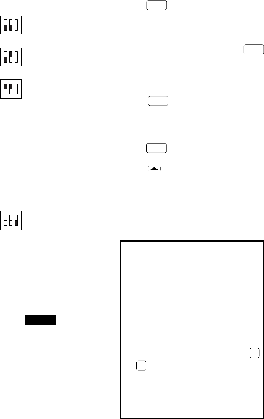
ON
123
Switch #1 OFF
Switch #2 OFF
Switch #3 (see step B5)
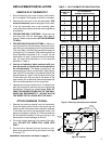
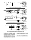
2. Manual Changeover (Heating/Cooling Systems
Only)
3. Heat Only Systems
4. Cool Only Systems
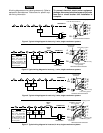
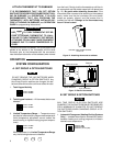
5. Computed Energy Management Recovery
(EMR) — With EMR enabled, system will be ener-
gized before the next program period begins, to
achieve programmed temperature by the beginning
of the next program period (the thermostat’s micro-
computer calculates 15 minutes for every 2°F tem-
perature change). For example, assume that the
thermostat is programmed to provide an overnight
heating temperature of 62°F, and during the next
program period, programmed to begin at 6:00 AM, the
programmed temperature is 70°F. With EMR acti-
vated, the thermostat will automatically activate the
heating system at 5:00 AM, so that the programmed
temperature of 70°F is reached by about 6:00 AM.
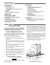
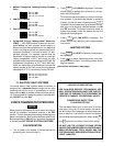
C. ELECTRIC HEAT SYSTEMS
For central electric heat systems where the blower is
energized by a separate circuit through the fan relay
(meaning that the fan turns on immediately on call for
heat), clip wire W14 on the back of the thermostat (see fig.
13). If the thermostat is energizing electric heat sequenc-
ers, DO NOT clip wire W14.
CHECK THERMOSTAT OPERATION
When checking thermostat, Group B option switches #1
and #2 for automatic changeover must be in the OFF
position. This will allow temporary setting of heat setpoints
above cool setpoints. After system checkout, reset Group
B option switch #1 to ON position if automatic changeover
is desired (see SET GROUP B OPTION SWITCHES).
FAN OPERATION
1. Turn on power to the system. If the heat source has
a standing pilot, be sure to light it.
2. Press
FAN
SWITCH
until FAN ON is displayed. The blower
should begin to operate (this will work only on sys-
tems with a G terminal).
On three-wire heat only systems, or on four-wire heat/
cool systems, if the thermostat display is operating
properly, but the fan does not operate when
FAN
SWITCH
is pressed, the red jumper wire (provided with thermo-
stat) may not be properly installed between the RH
and RC terminals. Disconnect electrical power to
system and properly install the jumper wire per the
appropriate wiring diagram.
3. Press
FAN
SWITCH
until FAN AUTO is displayed. The
blower should stop operating within approximately
one minute.
HEATING SYSTEM
1. Press
SYSTEM
SWITCH
until HEAT is displayed (it may already
be displayed).
2. Press to adjust thermostat above room tem-
perature to call for heat. The heating system should
begin to operate.
(Instructions continue on next page.)
LOCKOUT BYPASS OPTION
FOR QUALIFIED SERVICE TECHNICIANS’ USE
ONLY. OPERATORS SHOULD NOT USE THIS FEA-
TURE DUE TO POSSIBILITY OF EQUIPMENT OR
PROPERTY DAMAGE, OR PERSONAL INJURY.
COMPRESSOR SHORT TERM
CYCLE PROTECTION
This thermostat has a built-in short term (5-minute)
time delay. During this 5-minute period, the thermo-
stat will lock out the compressor to allow head pres-
sure to stabilize. If you want to override this feature
while testing thermostat operation, simply press
ADV
PRGM
and
HOLD
TEMP
buttons at the same time at initial startup.
DO NOT USE THE LOCKOUT BYPASS OPTION
UNLESS THE COMPRESSOR OIL HEATERS HAVE
BEEN OPERATIONAL FOR 6 HOURS AND THE
SYSTEM HAS NOT BEEN OPERATIONAL FOR AT
LEAST 5 MINUTES.
ON
123
Switch #1 OFF
Switch #2 ON
Switch #3 (see step B5)
ON
123
Switch #1 ON
Switch #2 ON
Switch #3 (see step B5)
ON
123
Switch #1 (see steps B1–B4)
Switch #2 (see steps B1–B4)
Switch #3 OFF
NOTE