


2
SPECIFICATIONS
ELECTRICAL DATA
Electrical Rating:
17 to 30 VAC, 50/60 Hz.
0.05 to 1.5 Amps
1.5 Amps Maximum Total Load (All terminals
combined)
Anticipation:
Heating 2 to 40
Cooling 4 to 40
THERMAL DATA
Setpoint Temperature Range:
40°F to 99°F (4°C to 37°C)
Operating Ambient Temperature Range:
32°F to 105°F
Operating Humidity Range:
0 to 90% RH (non-condensing)
Shipping Temperature Range:
-40°F to 150°F
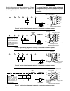
APPLICATIONS
For use with:
• Standard heat/cool or heat-only systems
• Three-wire zone valve systems
• Millivolt systems
• Electric heat systems
• Gas or oil fired systems
• Gas systems with intermittent ignition devices
(I.I.D.) and/or vent dampers
Do not use with:
• Multi-stage systems
• Heat pump systems
• Systems exceeding 30 VAC and 1.5 Amps
ACCESSORIES
Remote Sense Kit W. R. Part No. F145-1049
Thermostat Guard W. R. Part No. F29-0198 (clear)
or F29-0238 (opaque)
}
Reference Values
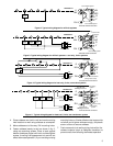
INSTALLATION
NEW INSTALLATION
You should program the thermostat with batteries
installed before attaching on subbase. See OPERA-
TION GUIDE for programming instructions.
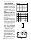
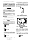
SELECT THERMOSTAT LOCATION
Proper location insures that the thermostat will provide a
comfortable building temperature. Observe the following
general rules when selecting a location:
1. Locate thermostat about 5 ft. above the floor.
2. Install thermostat on a partitioning wall, not on an
outside wall.
3. Never expose thermostat to direct light from lamps,
sun, fireplaces or any temperature radiating equip-
ment.
4. Avoid locations close to windows, adjoining outside
walls, or doors that lead outside.
5. Avoid locations close to air registers or in the direct
path of air from them.
6. Make sure there are no pipes or duct work in that part
of the wall chosen for the thermostat location.
7. Never locate thermostat in a room that normally
warmer or cooler than the rest of the building.
8. Avoid locations with poor air circulation, such as
behind doors or in alcoves.
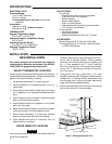
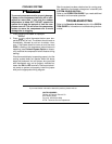
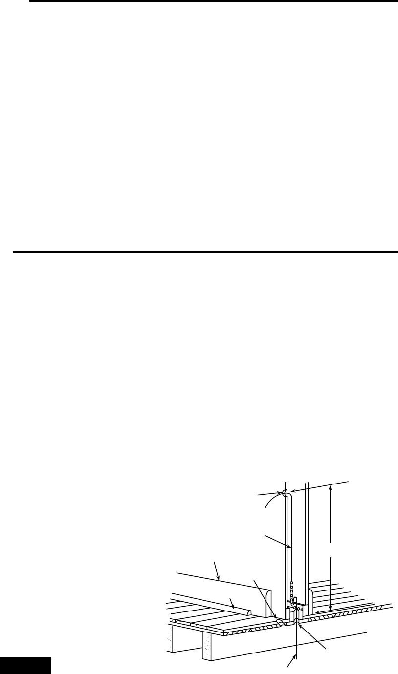
ROUTE WIRES TO LOCATION
All wiring must conform with local and national electrical
codes and ordinances.
1. Probe for obstructions in partition before drilling
1
⁄2”
hole in wall at selected location. Take up quarter
round and drill a small guide hole for sighting (see
fig. 1). From basement, drill
3
⁄4” hole in partition
floor next to guide hole. In buildings without base-
ments, drill
1
⁄2” hole through ceiling and into parti-
tion from above.
2. Through this hole drop a light chain, or 6” chain
attached to a strong cord. Snag cord in basement with
hooked wire. In buildings without basements, drop
cord through hole in ceiling and down partitioning;
snag cord at the thermostat location.
3. Attach thermostat wire to cord and pull wire through
hole in wall so that 6” of wire protrudes.
NOTE
Approximately
5 feet from floor
1
⁄
2
” hole for
thermostat wire
Stout cord with 6”
chain attached
Baseboard
strip moulding
1
⁄
4
” guide hole
for sighting
Quarter round
removed
3
⁄
4
” hole in floor of partition
Hooked wire for snagging chain
Figure 1. Routing thermostat wires