


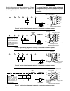
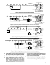
5
RH
Y
MV
24 VAC
120 VAC
Hot
Neutral
THERMOSTAT
SYSTEM
G W
HEATING TRANSFORMER
6
24 VAC
120 VAC
Hot
Neutral
COOLING TRANSFORMER
Cooling
System
Fan
Relay
Heating
System
RC
G
RC
6
MV
Y
W
RH
Thermostat Terminal Connections
From fan relay
From heating
system
From 24 VAC
cooling transformer
From cooling
system
From 24 VAC
heating transformer
Figure 11. Typical wiring diagram for heat/cool, 5-wire, two-transformer system
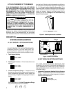
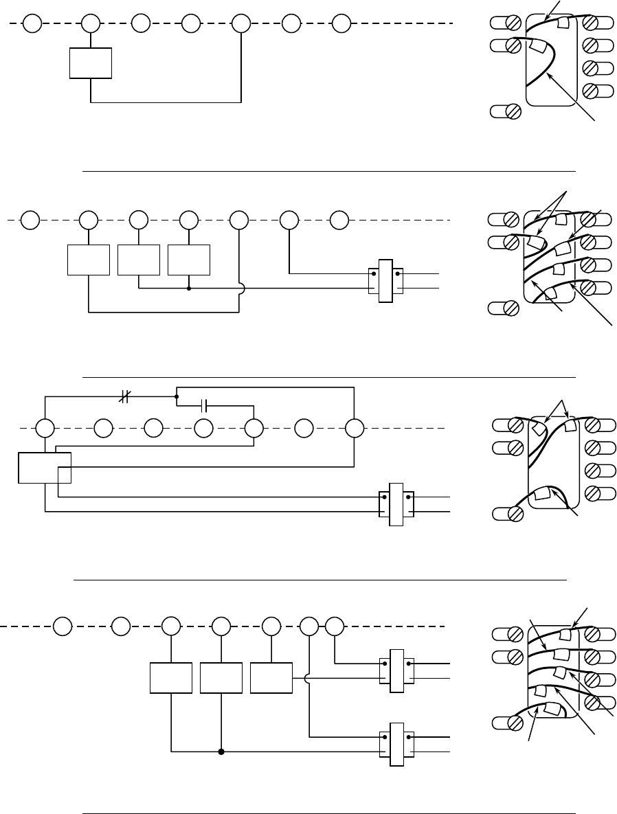
RH
W
RC
G
Y
RH
Y
MV
24 VAC
120 VAC
Hot
Neutral
THERMOSTAT
SYSTEM
G W
Figure 10. Typical wiring diagram for heat only, 3-wire, zone valve systems
TRANSFORMER
6
Zone
Valve
64
5
21
RC
G
RC
6
MV
Y
W
RH
Thermostat Terminal Connections
From 24 VAC transformer
(through zone valve)
W
From zone valve
RH
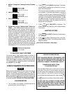
6
RH
Y
MV
THERMOSTAT
SYSTEM
G W
Figure 9. Typical wiring diagram for millivolt systems + cool only, 3-wire systems
6
Millivolt
System
RC
G
RC
6
MV
Y
W
RH
Thermostat Terminal Connections
From fan relay
W
From millivolt system
MV
Cooling
System
Fan
Relay
24 VAC
120 VAC
Hot
Neutral
TRANSFORMER
RC
G
Y
From cooling system
From 24 VAC
transformer
4. Place subbase over hole in wall and mark mounting
hole locations on wall using subbase as a template.
5. Move subbase out of the way. Drill mounting holes.
6. Fasten subbase loosely to wall, as shown in fig. 3,
using two mounting screws. Place a level against
bottom of subbase, adjust until level, and then tighten
screws. (Leveling is for appearance only and will not
affect thermostat operation.) If you are using existing
mounting holes, or if holes drilled are too large and do
not allow you to tighten subbase snugly, use plastic
screw anchors to secure subbase.
7. Push excess wire into wall and plug hole with a fire-
resistant material (such as fiberglass insulation) to
prevent drafts from affecting thermostat operation.
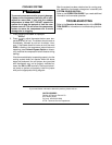
RH
Y
MV
THERMOSTAT
SYSTEM
G W
Figure 8. Typical wiring diagram for millivolt systems
6
Millivolt
System
RC
G
RC
6
MV
Y
W
RH
Thermostat Terminal Connections
From millivolt system
W
From millivolt system
MV