


5
OPERATION
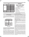
OPTION SWITCHES
The option switches on the 50A66-843 control are used
to determine the length of the heat delay-to-fan-off and
cool-delay-to-fan-off periods. The following table shows
the time periods that will result from the various switch
positions.
HEAT delay-
to-fan-off:
Set switch
#1 #2
60 sec.
90 sec.*
120 sec.
180 sec.
Off Off
Off On
On Off
On On
COOL delay-
to-fan-off:
Set switch
#3
2 sec.
45 sec.*
*Factory Setting
Off
On
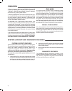
OPTION SWITCH POSITIONS
HEAT MODE
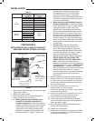
In a typical system, a call for heat is initiated by closing the
thermostat contacts. This starts the 50A66-843 control’s
heating sequence. The inducer blower and humidifier are
energized. After a 15-second pre-purge period, the 768A
Silicon Nitride ignitor is powered.
This controller has an adaptive algorithm that reduces
ignitor temperature to slightly greater than the minimum
temperature required to ignite gas in each particular
application. The control measures the line voltage and
determines an initial ignitor temperature setting based
on the measurement. After each successful ignition, the
control lowers the ignitor temperature slightly for the next
ignition attempt. The control continues to lower the ignitor
temperature until ignition does not occur, and the control
goes into retry mode. For the second attempt to ignite
gas within the same call for heat, the control increases
the ignitor temperature to the value it was on the third
previous successful ignition. After ignition is successful,
the control sets the ignition temperature at this value for
the next 255 calls for heat, after which the control repeats
the adaptive algorithm. The control is constantly making
adjustments to the ignitor temperature to compensate for
changes in the line voltage.
The 80 VAC Silicon Nitride ignitor manufactured by
White-Rodgers must be used. These ignitors are spe-
cially designed to operate with the 50A66-843's adap-
tive ignition routine to ensure the most efficient ignitor
temperature.
At the end of the ignitor warm-up time, both valves in the
gas valve are opened. Flame must be detected within 4
seconds.
If flame is detected, the delay-to-fan-on period begins.
After the delay-to-fan-on period ends, the circulator fan is
energized at heat speed. If there is an optional electronic
air cleaner on the system, the electronic air cleaner and
the humidifier are energized. When the thermostat is
satisfied, the gas valve is de-energized. After proof of
flame loss, the inducer blower remains energized to purge
the system for 5 seconds and the delay-to-fan-off period
begins. When the purge is complete, the inducer blower
and humidifier are de-energized. After the delay-to-fan-off
period ends, the circulator fan and electronic air cleaner
are de-energized.
If flame is not detected, both valves are de-energized,
the ignitor is turned off, and the 50A66-843 control goes
into the “retry” sequence. The “retry” sequence provides a
15-second wait following an unsuccessful ignition attempt
(flame not detected). After this wait, the ignition sequence
is restarted. If this ignition attempt is unsuccessful, three
more retries will be made before the control goes into
system lockout.
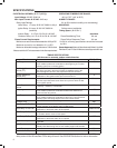
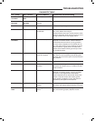
TABLE 2
Type Existing
Control Board
Replacement
Control Board
L1
120 VAC
ACB COOL COOL
ACB HEAT HEAT
PARK M1 PARK
PARK M2 PARK
ACC EAC
120 VAC HOT LINE
120 VAC TX XFMR
HTG ACC HUM
ACB LOW FAN
Neutral
120 VAC
Neutral 120 VAC
Return (5)
Neutral
120 VAC (5)
Flame Sense E33 FS
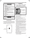
PROCEDURE 3
REPLACING 100925-01, 100925-02,
100925-03, 17W9201, 23W5101,
30W2501, 50A66-122, 50A66-123,
69M0801 or 69M1501
1. Disconnect all electric power and shut off gas
supply to the furnace.
2. Remove the access panel
3. Disconnect wiring and remove existing ignition
control board.
4. Insert the replacement board into existing holes.
5. Reconnect wiring.
6. Replace access panel.
7. Restore the electrical power and gas supply. Refer
to the furnace installation instructions for start-up
and check-out procedures.
INSTALLATION