


4
INSTALLATION
over the marks. Use the mounting panel
as a template to drill 3/16" holes through
each of the holes marked "A". Install the
replacement control in the freshly drilled holes
in the blower access panel. Use aluminum tape
to seal the unused holes.
B. When replacing original 63K8901 board in
downowapplications – Look at the existing
control board holes as if the unit were installed
in the upflow position. Make a mark 5/8"
ABOVE each of the existing mounting holes.
Position the provided mounting panel so that
the holes marked "C" in figure 1, page 3 are
over the marks. Use the mounting panel as a
template to drill 3/16" holes through each of
the holes marked "A". Install the replacement
control in the freshly drilled holes in the blower
access panel. Use aluminum tape to seal the
unused holes.
C. All other units – Position the provided
mounting panel so that the arrow on the
front of the panel is pointing up. Position the
replacement 50A66-843 ignition control board
over the holes marked "A" in figure 1, page 3.
Insert the replacement control stand-off
fasteners into the holes in the mounting panel.
80UHG, 90UGF, G23, G26, GHR26, G32,
GHR32, G40, G41, G50, G51, G60 and G61
units – Insert the four provided stand-off
fasteners into the back of the mounting panel in
the holes marked "B" in figure 1. 80MGF, G24M
and G27M units – Insert the four provided
stand-off fasteners into the back of the mounting
panel into the holes marked "C" in figure 1.
Insert the replacement control board assembly
into the existing holes in the control box or
blower panel.
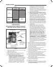
5. Insert provided circuit breaker in series between
the blue wire on Pin 3 of the wiring harness (9-pin
to 12-pin) and the blue transformer wire. Optional
4" blue wire provided for transformers that have a
quick-connect terminal.
6. Connect the provided 9-pin to 12-pin wiring
harness to the unit 9-pin connector.
7. Connect the provided 4-pin to 6-pin wiring harness
to the unit 6-pin connector.
8. Connect the yellow wire from position 6 on the 12-
pin connector to the yellow transformer wire.
9. Connect GND wire to equipment ground.
10. Connect the remaining 120 VAC hot and neutral
wires and the flame sense wire to the replacement
control per table 2, page 5 .
11. Affix wiring diagram 5001-6972 adjacent to the
existing unit wiring diagram
12. Replace the access panel.
13. Restore the electrical power and gas supply. Refer
to the furnace installation instructions for start-up
and check-out procedures.
1. Disconnect all electrical power and shut off the gas
supply to the furnace.
2. Remove the access panel.
3. Disconnect wiring and remove existing ignition
control board from the control box.
4. A. When replacing original 63K8901 board
inupoworhorizontalapplicationsor
downowapplications – Look at the existing
control board holes as if the unit were installed
in the upflow position. Make a mark 1" to the
right of each of the existing mounting holes.
Position the provided mounting panel so that
the holes marked "C" in figure 1, page 3 are
Optional 4" blue
wire to connect to
Transformer (TH)
Circuit breaker
in series between
Pin 3 and Trans-
former (TH)
Wiring harness
(4-pin to 6-pin)
Mounting panel
Wiring harness
(9-pin to 12-pin)
Transformer
GND
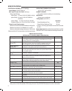
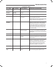
TABLE 1
Type Existing
Control Board
Replacement
Control Board
L1
120 VAC
COOL-H COOL
HEAT-H HEAT
PARK (2) PARK (2)
EAC-H EAC
LINE-H LINE
XFMR-H XFMR
HUM-H HUM
NONE FAN
Neutral
120 VAC
LINE-N
Neutral
120 VAC
(5)
HUM-N
EAC-N
XFMR-N
CIR-N
Flame Sense E33 FS
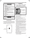
PROCEDURE 2
REPLACING 24L8501, 50A62-120, 50A62-121,
50A62-820, 56L8301, 63K8901 or 97L4801
Photo 2